Sunday 27 July 2014

Restoration of a walnut veneered mantel clock

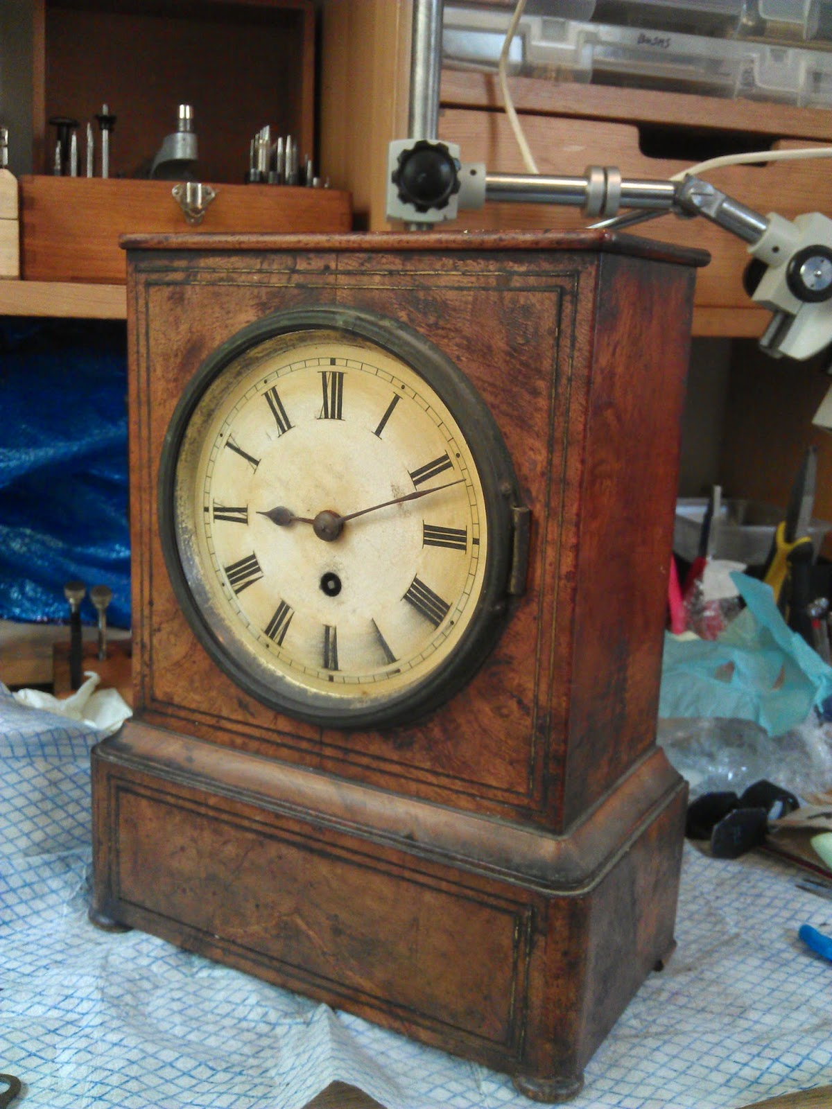
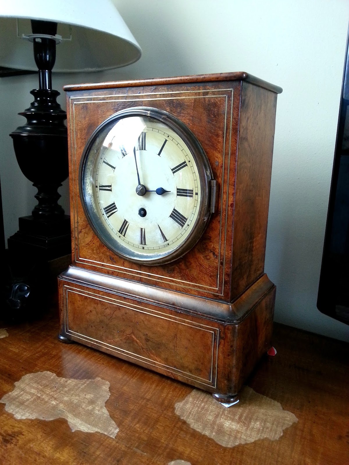
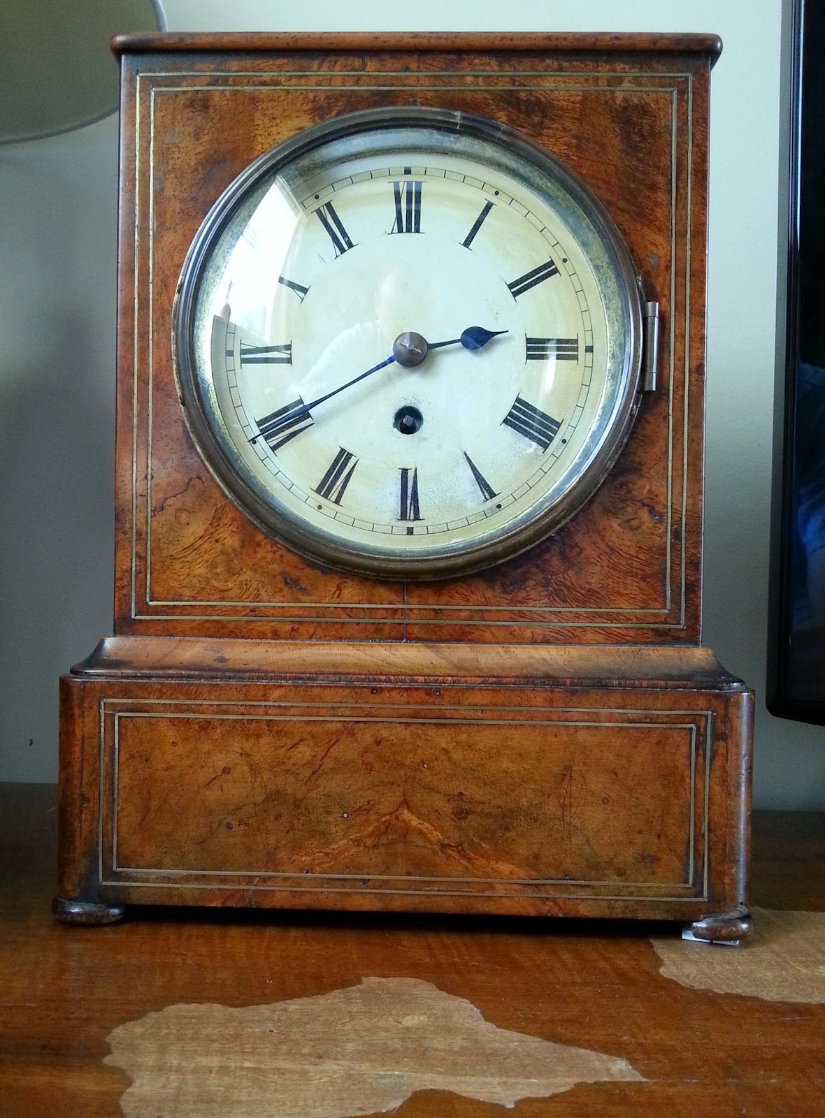
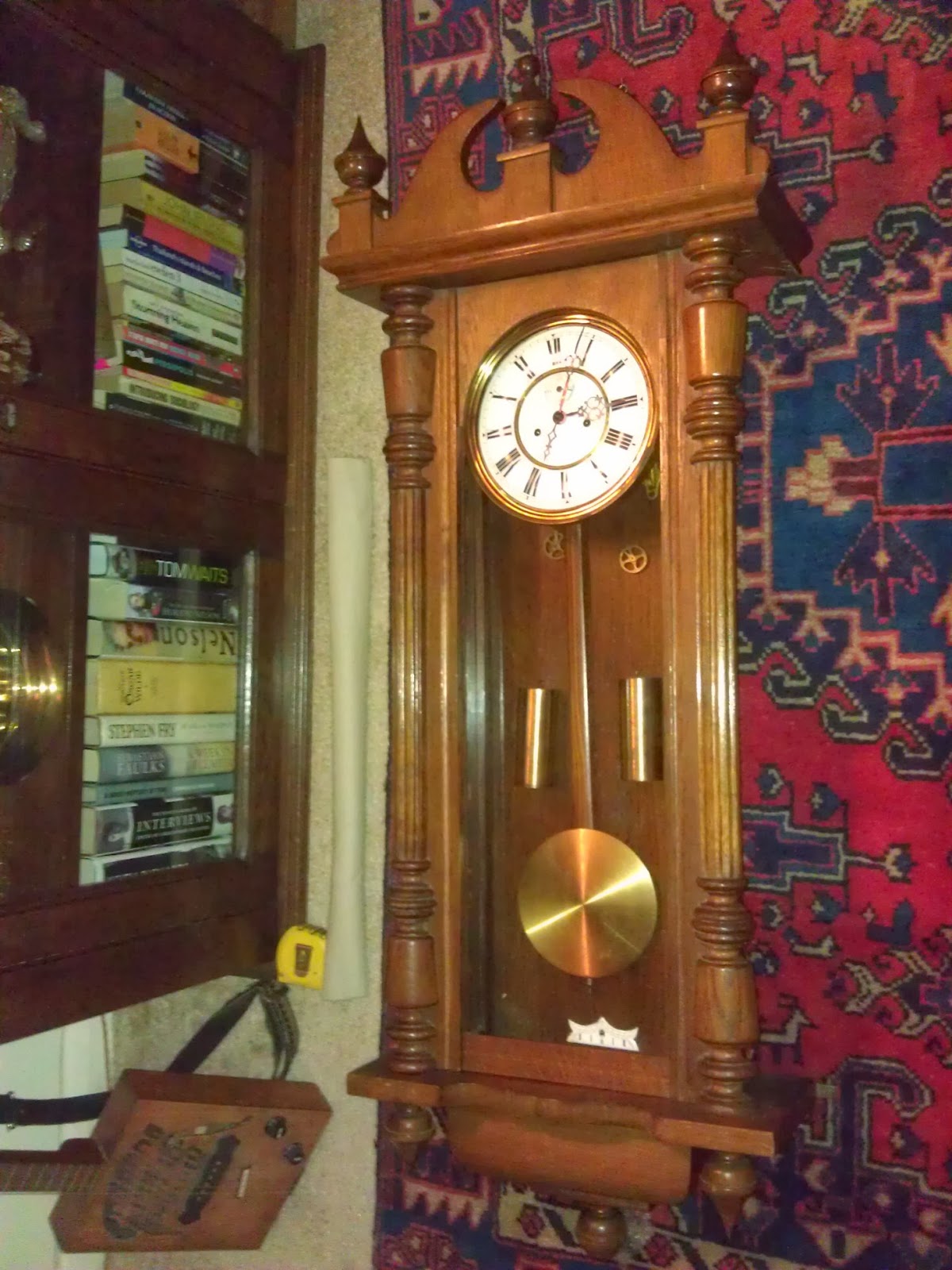
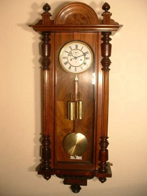
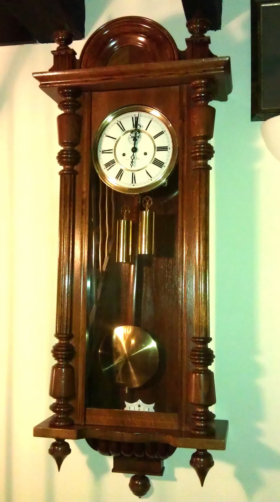
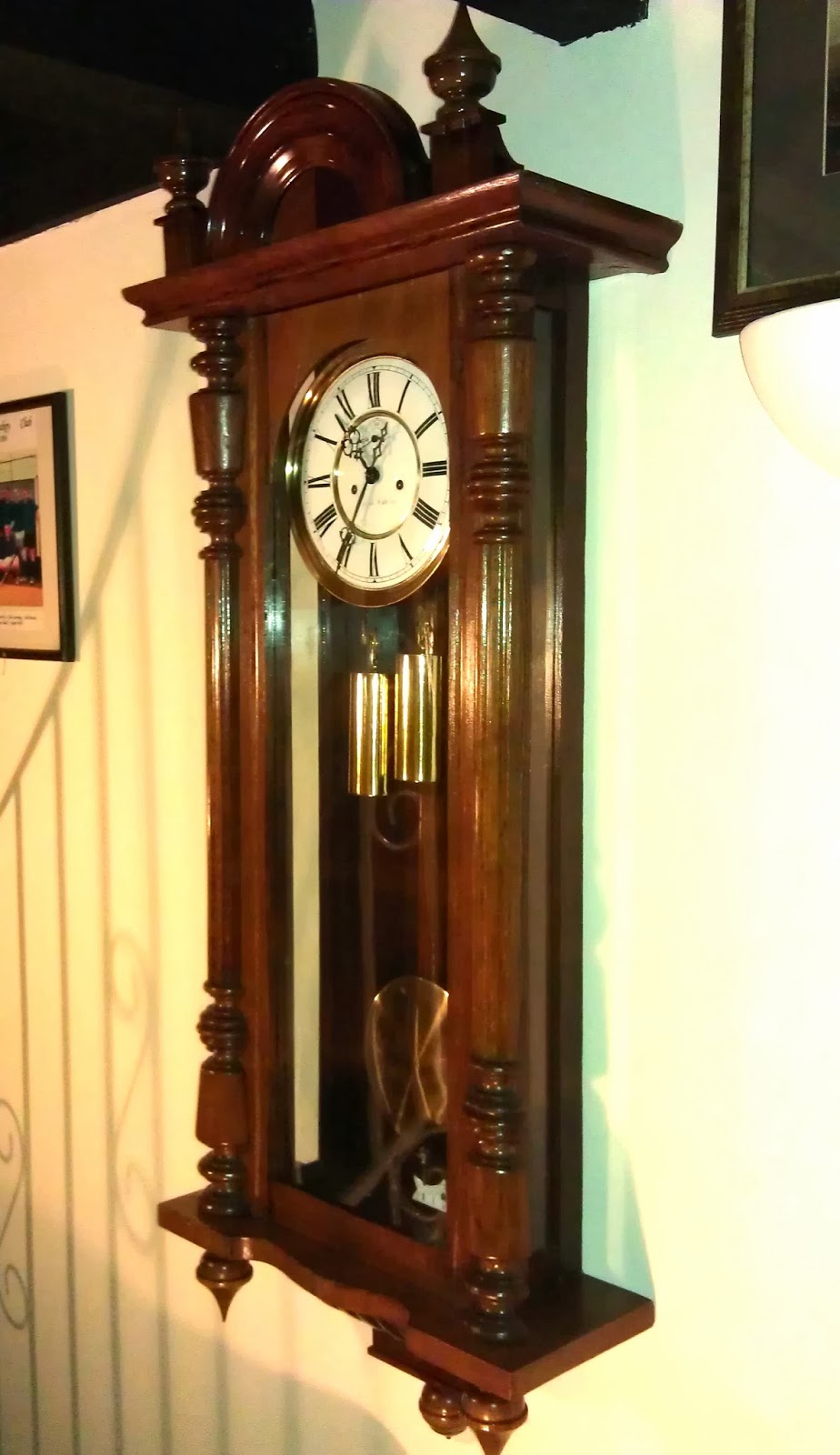
It was the Walnut finish of this simple mantel clock that caught my attention. Finished with fine brass inlay, the clock I feel has a Georgian appeal. Clearly its patina, and evidence of having spent some time without attention, had a great deal of appeal. 
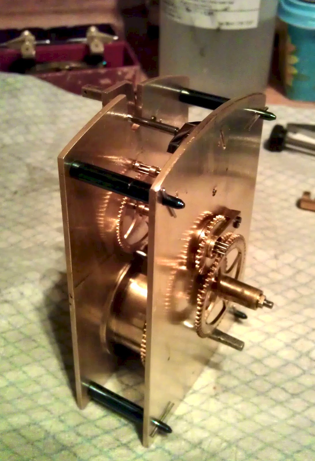
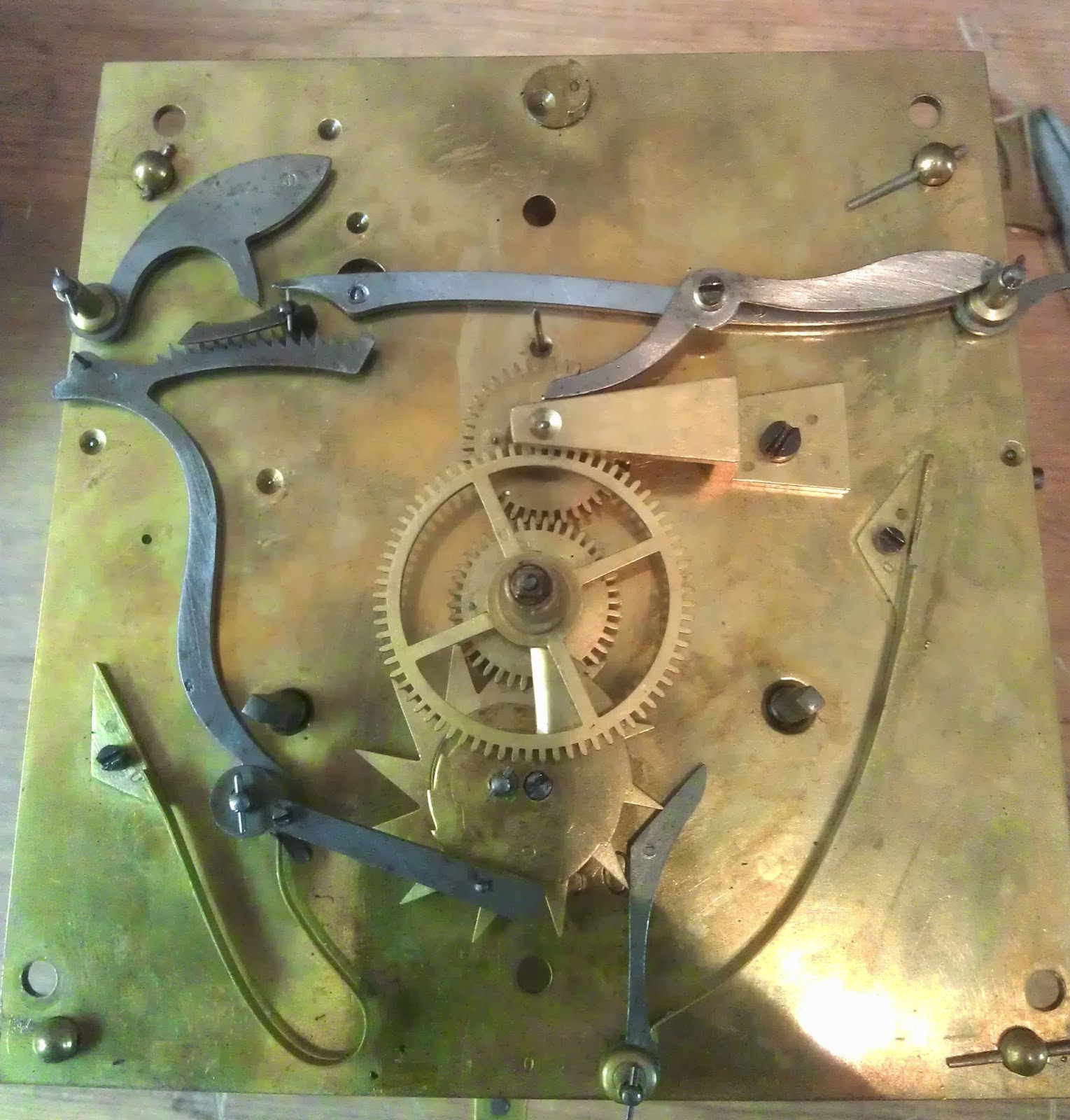
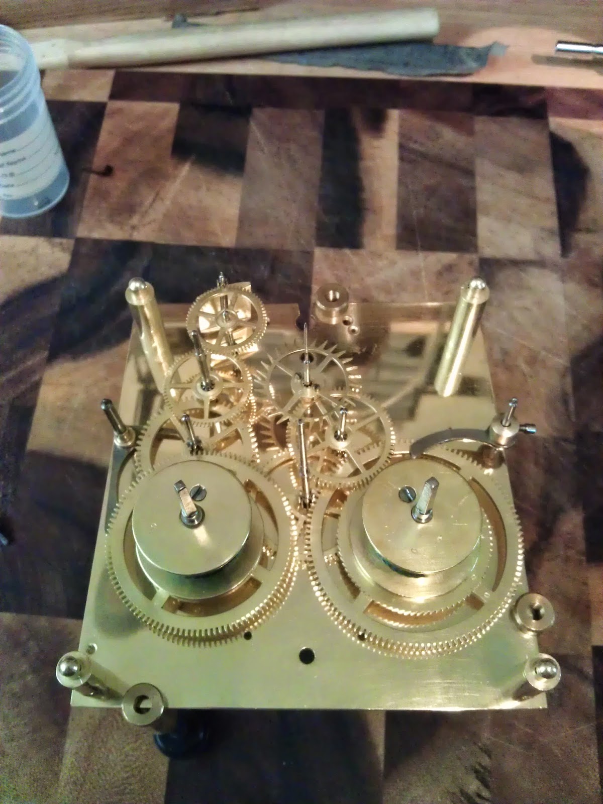
Examination of the movement has led me, and other friends from the horological world, to question if this movement is an early Winterhalder and Hofmeier, or if it is an English movement. Winterhalder and Hofmeier are known to have copied some English movements in their production. So the jury is out, if anyone has any comments regarding this please do email me.
The case would receive limited attention in order to retain its original appeal, pic 2 below shows brass inlay missing. The glass was missing, and there is evidence on a previous attempt to clean the dial. Smudging of the paint can be at numbers 4,5 and 6.
                  
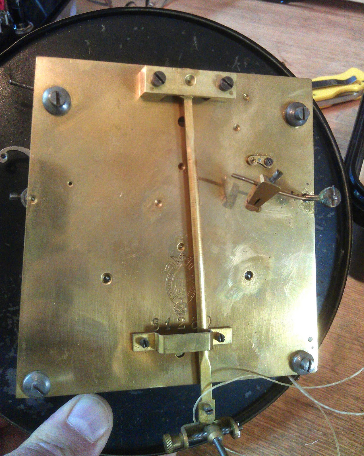
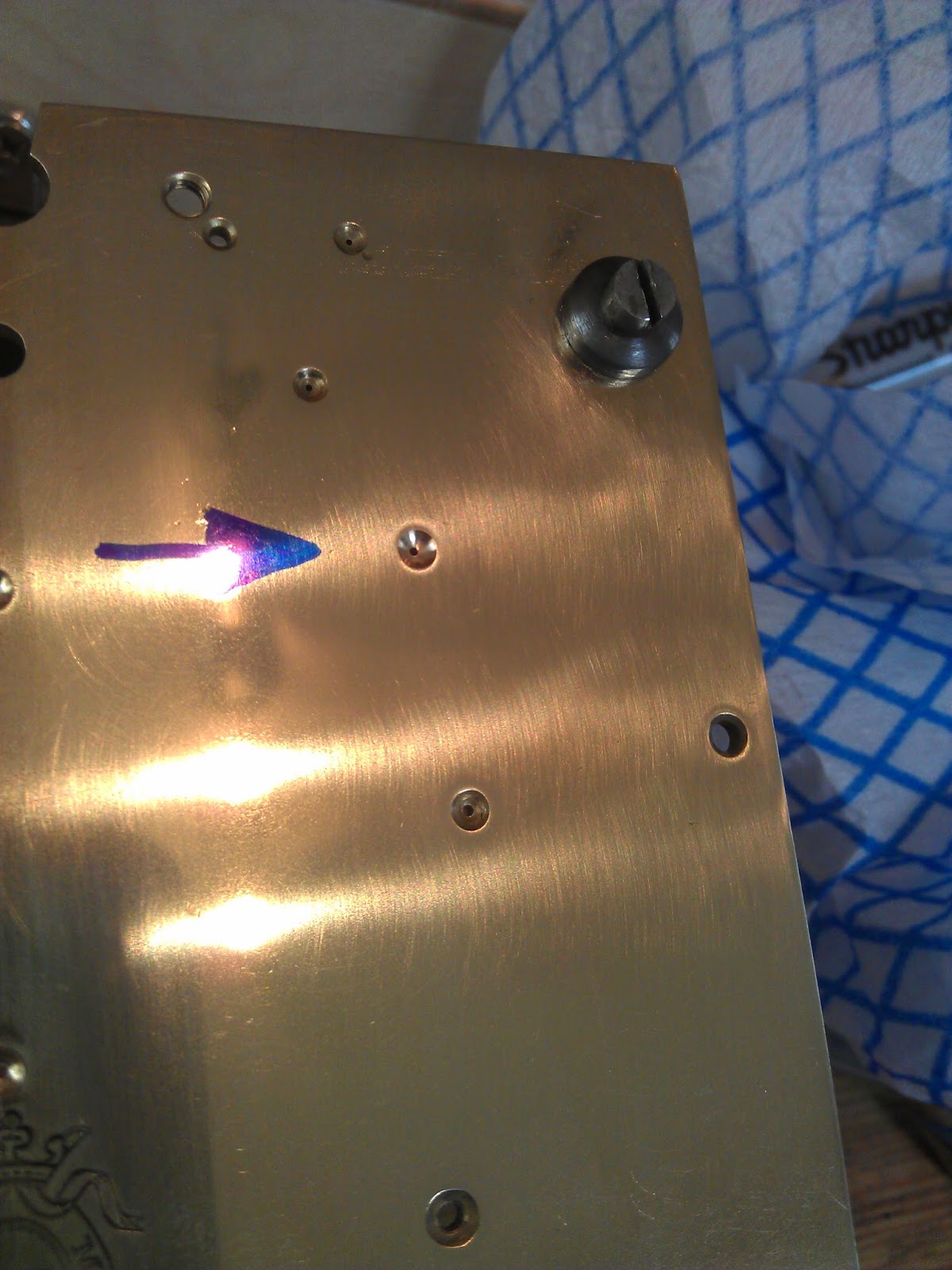
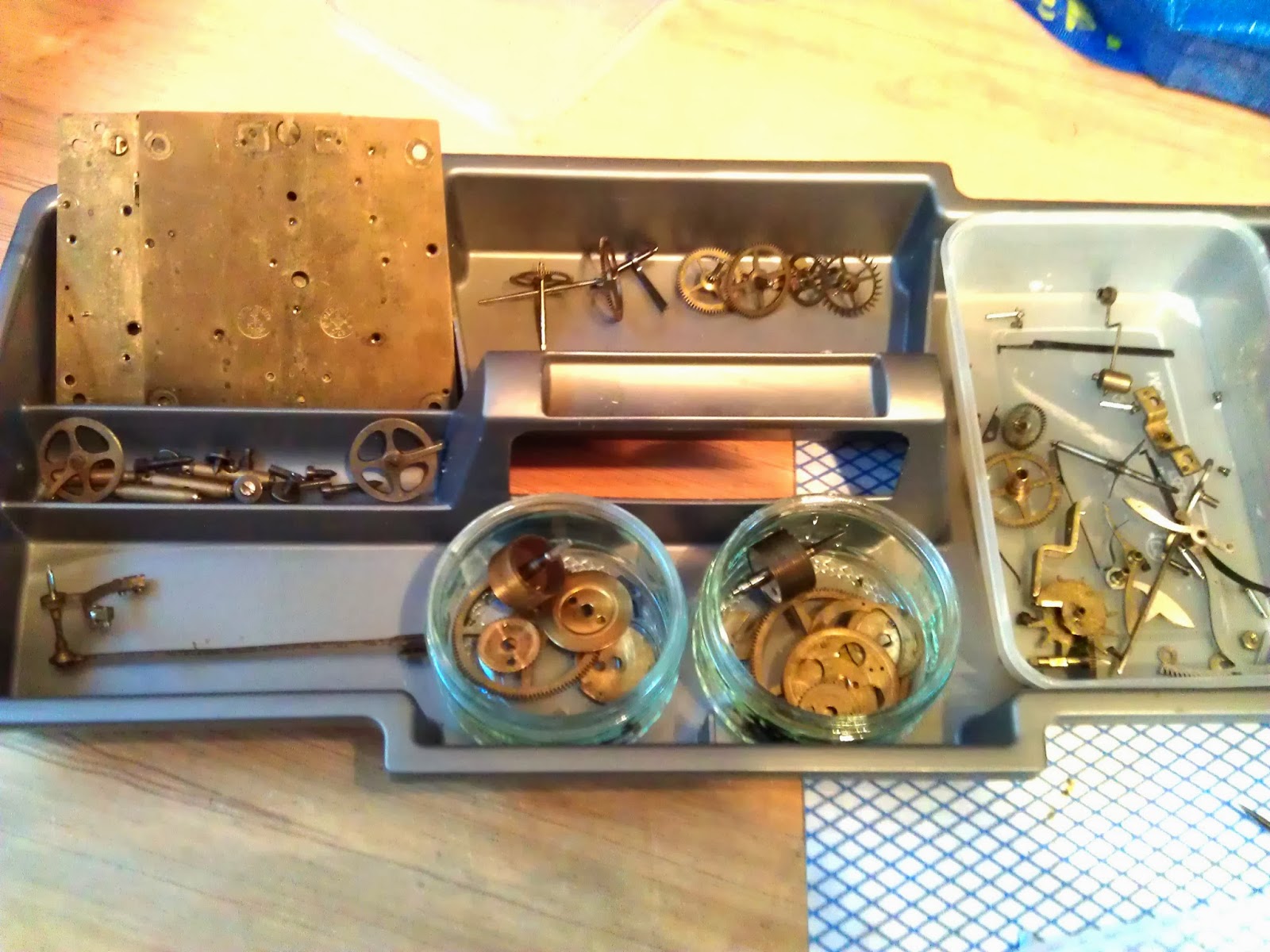
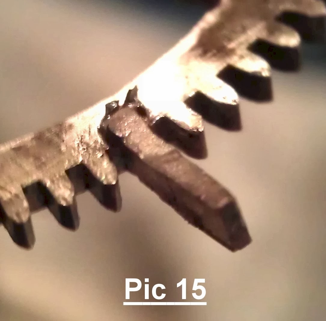
I noted that the stops works on the back plate of the movement, was damaged. The pictures below show that the pinion leafs have been filed off at some point. I would imagine that this was done to lengthen the running time of the clock. With the stop works complete it would run for approx 30hrs.

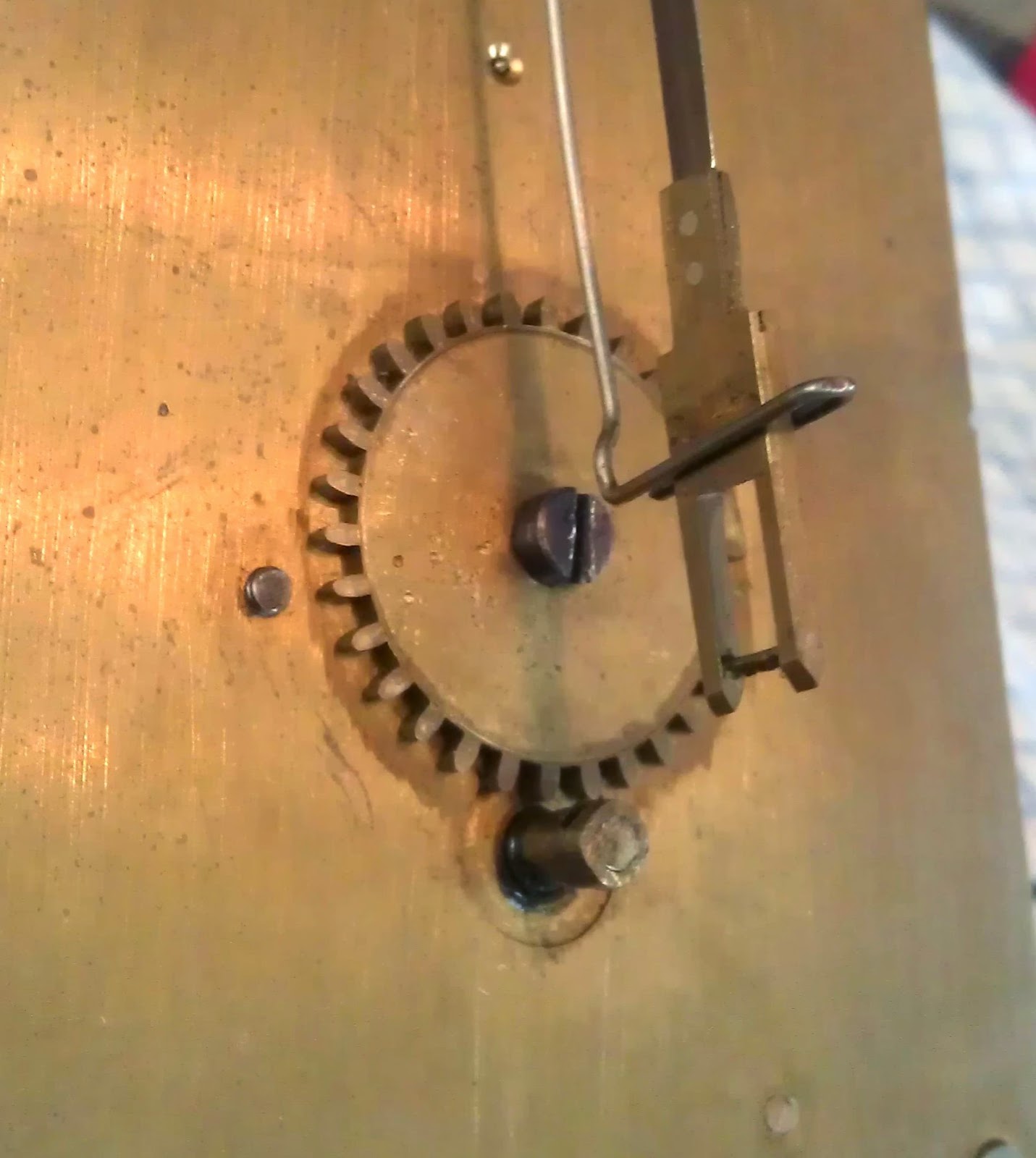
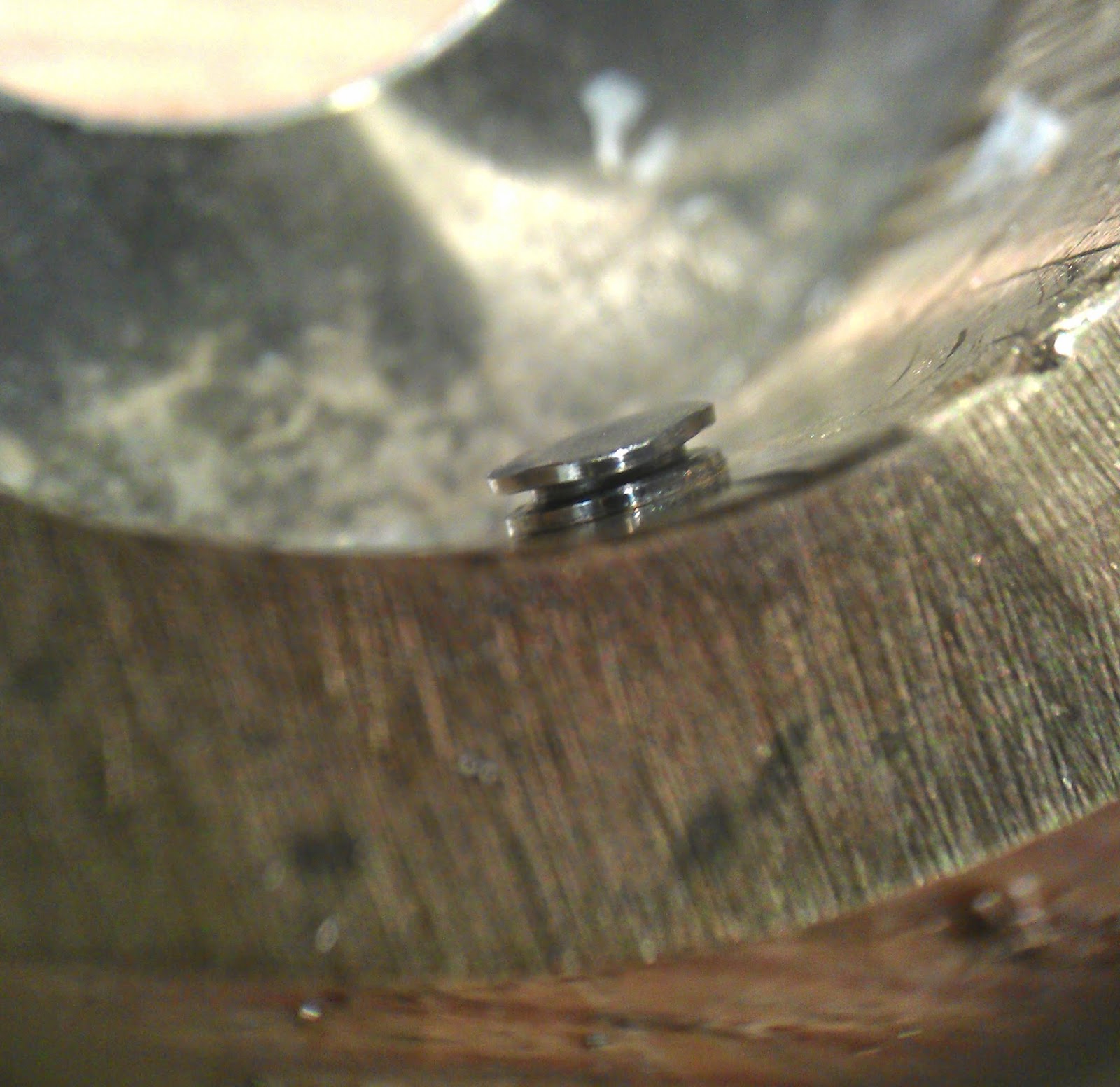
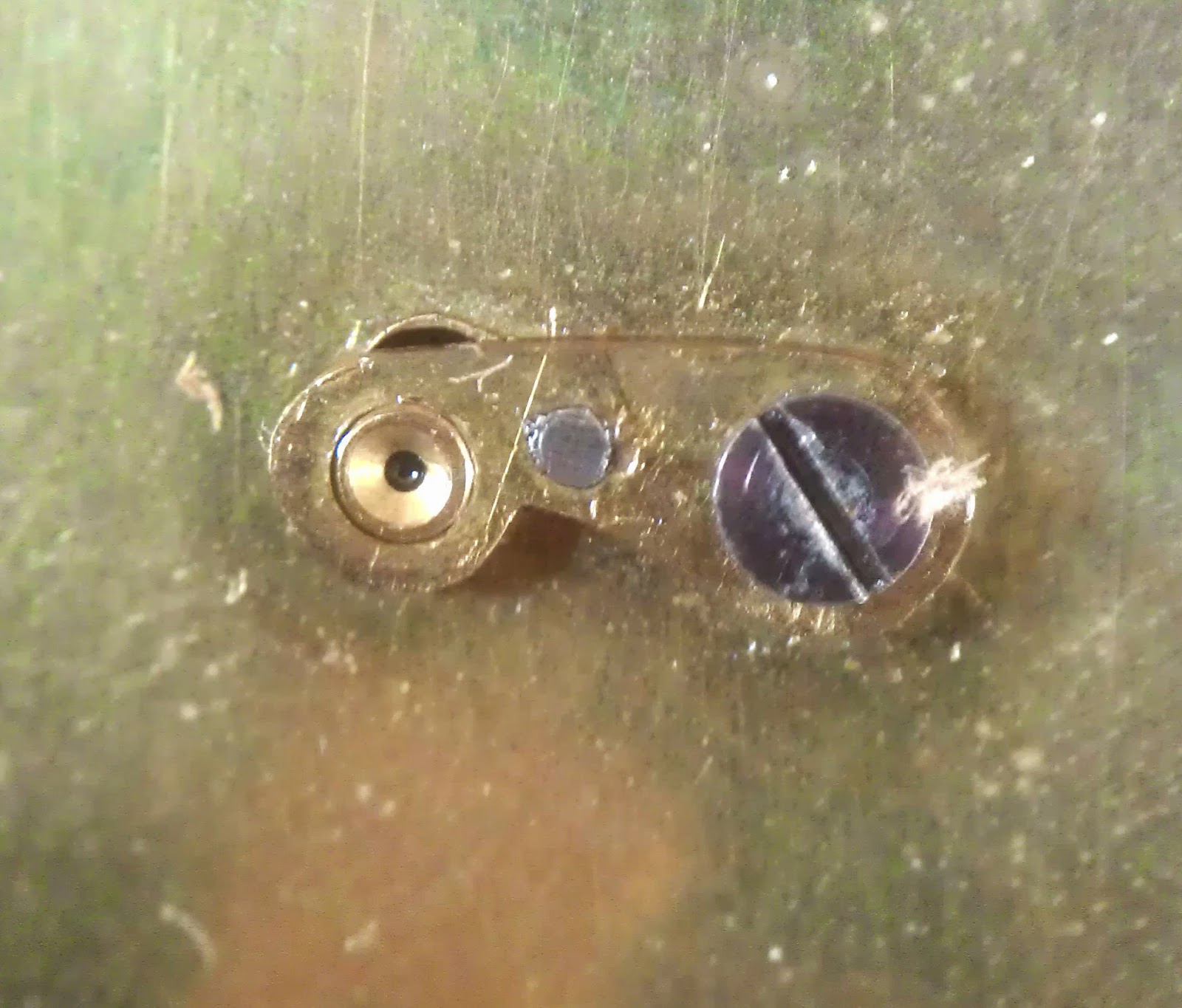
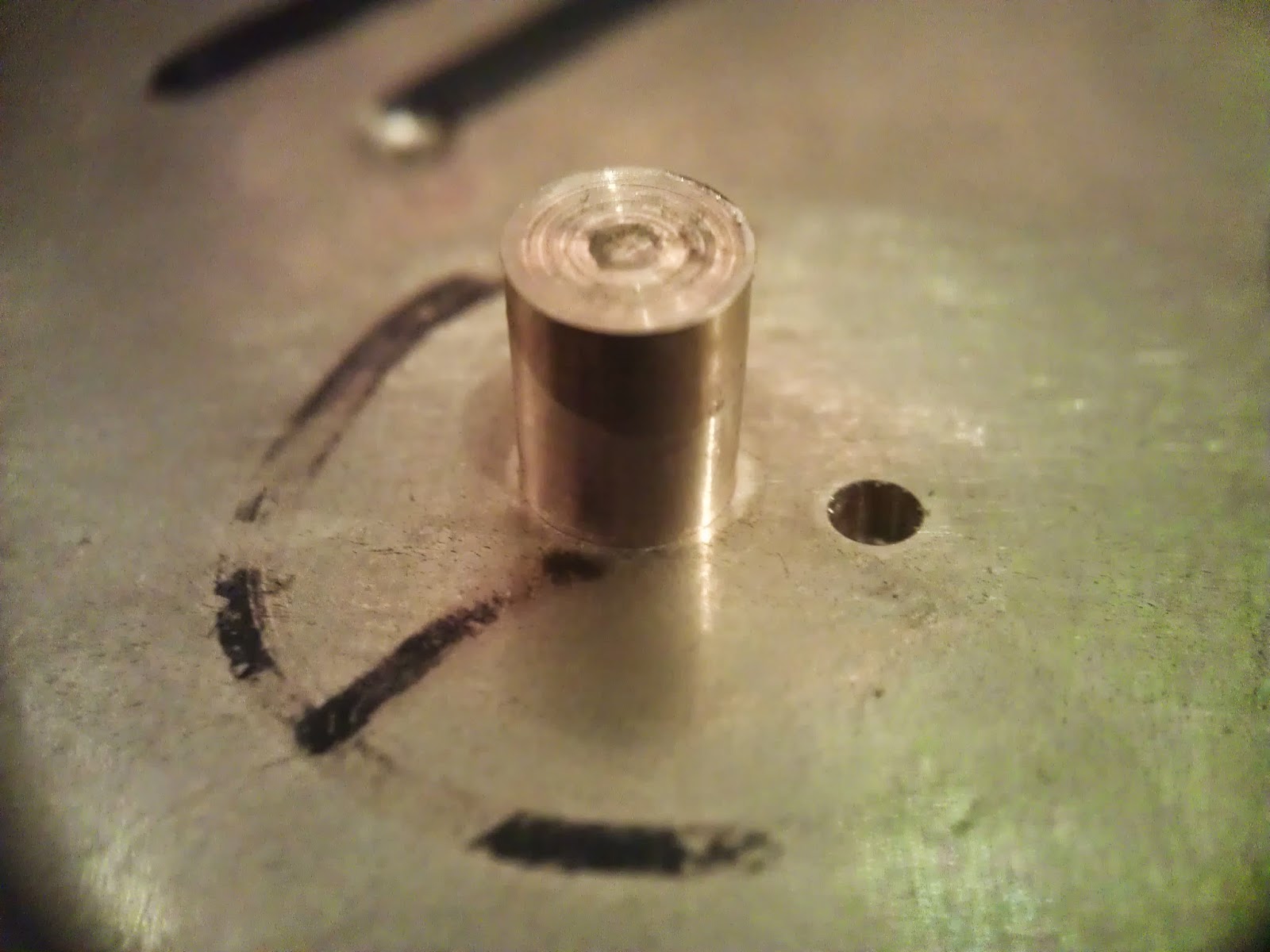
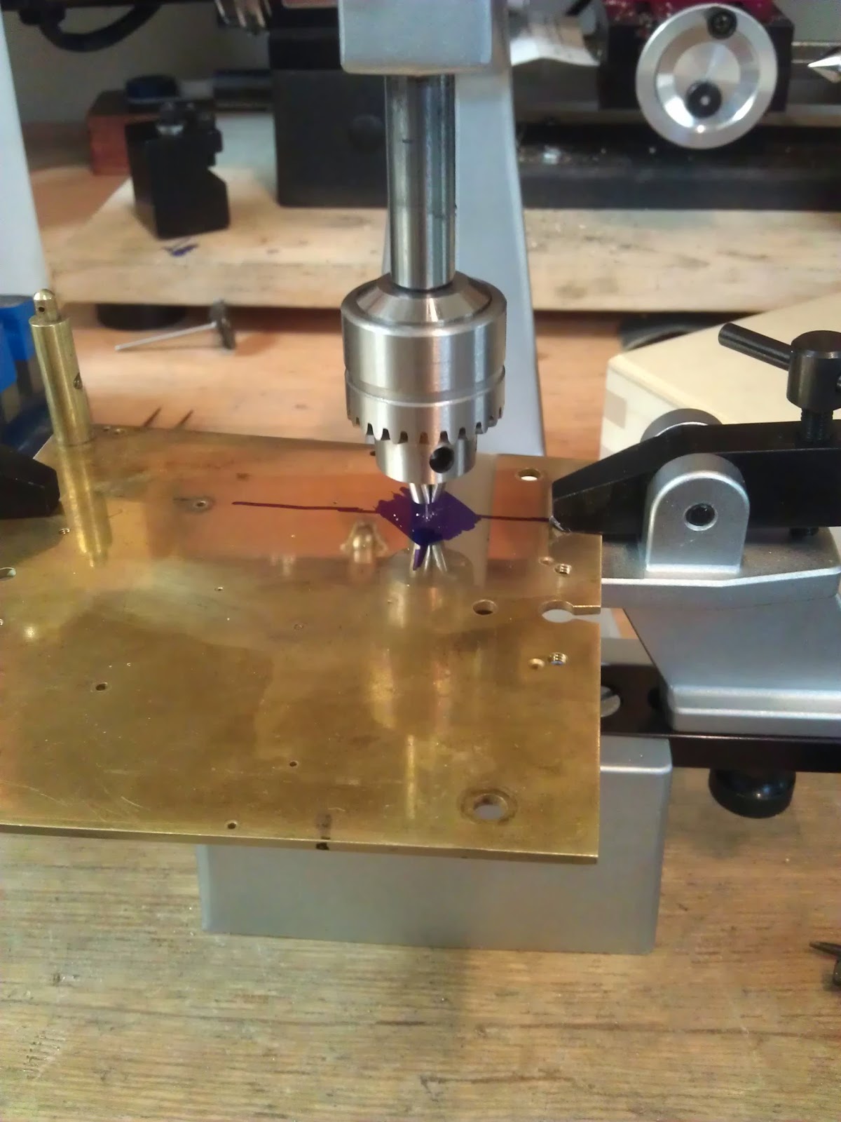
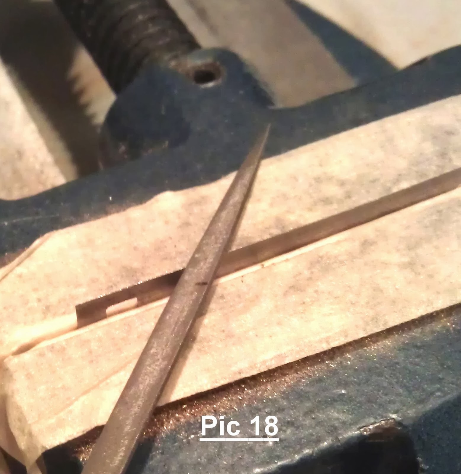
Whilst I appreciate the benefit of a longer running clock, sympathetically restoring to original where appropriate is preferred. To this end I handmade a replacement pinion for the stop works. The stops works would enable the movement to use a more consistent section of the springs power curve, by avoiding the use of the first two winds and the last few winds. So, in theory, be a better time keeper. Completed pinion below, with a hole for fitting to its post with a pin.
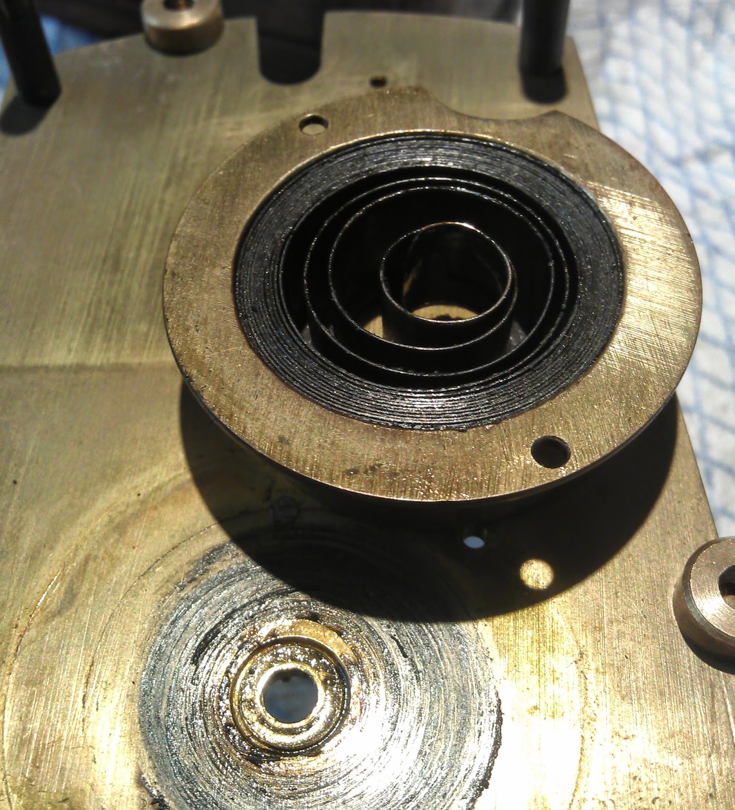
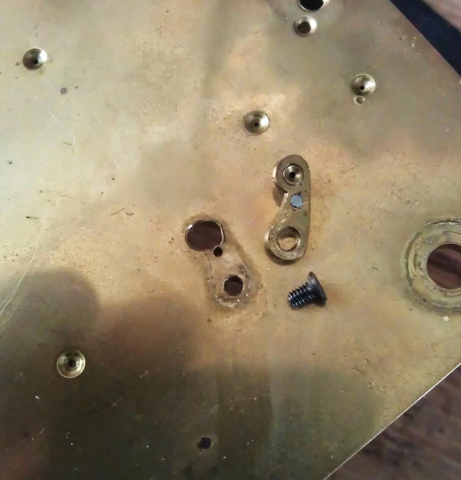
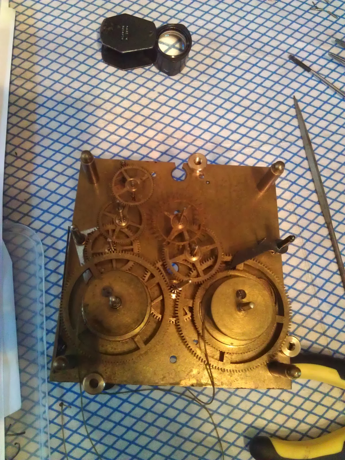
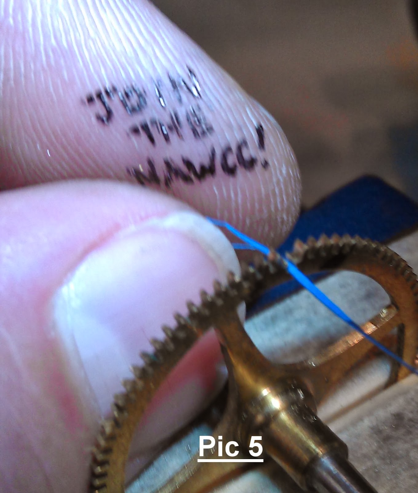
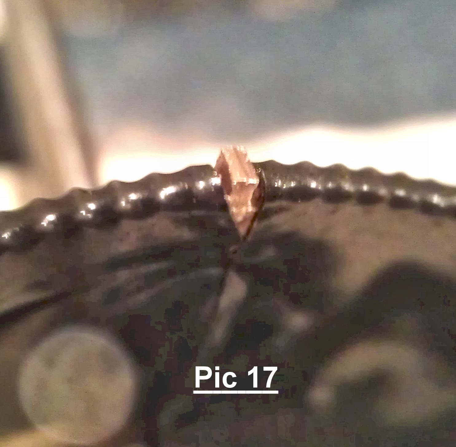
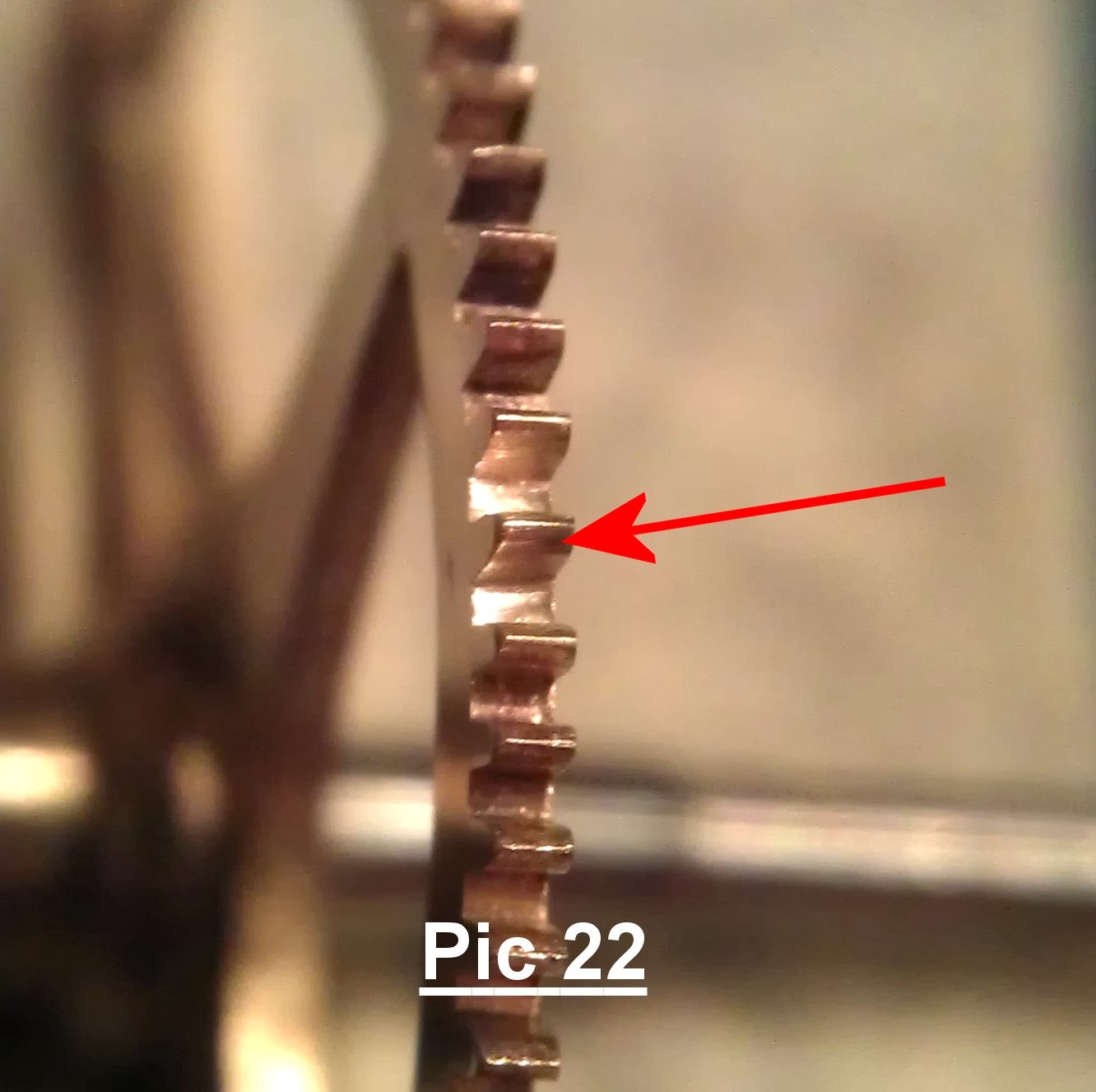
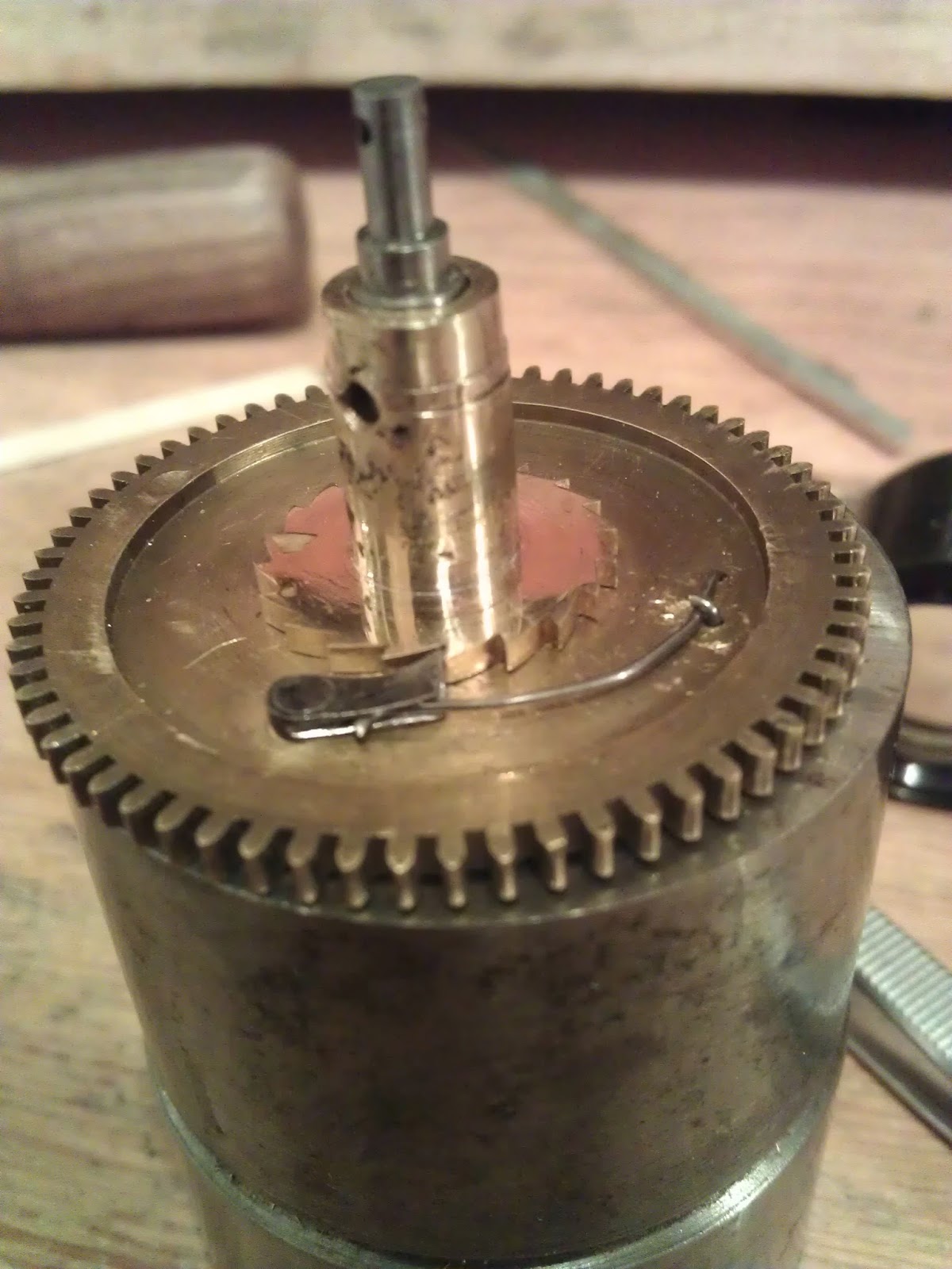
I heard some 'rattles' coming from the bottom of the case, and on closer inspection, I found a number of small brass teeth. This would explain why the winding arbour turned without resistance. They would be the teeth from the ratchet wheel, having suffered a spring incident. The pictures below show the state of the internal ratchet wheel, with missing teeth, and the 'hung' spring barrel. The 'hung barrel' is fixed to the clock plate.


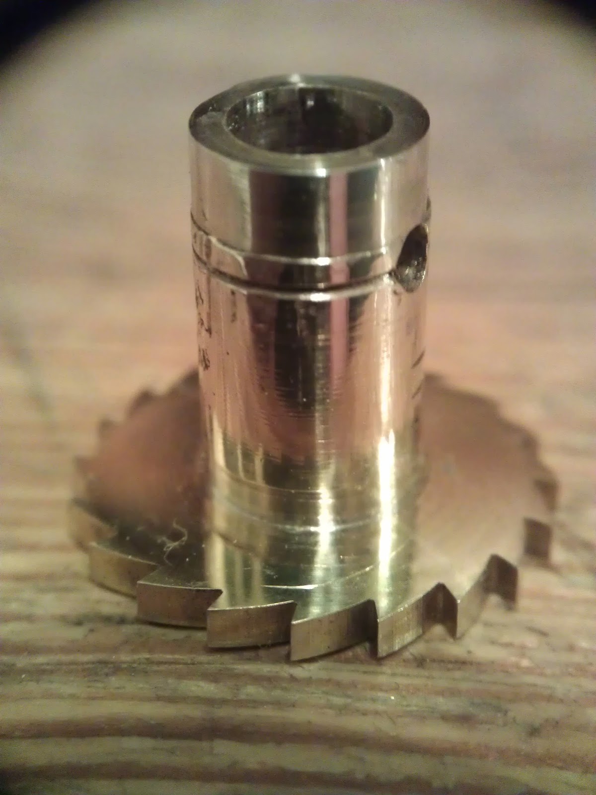
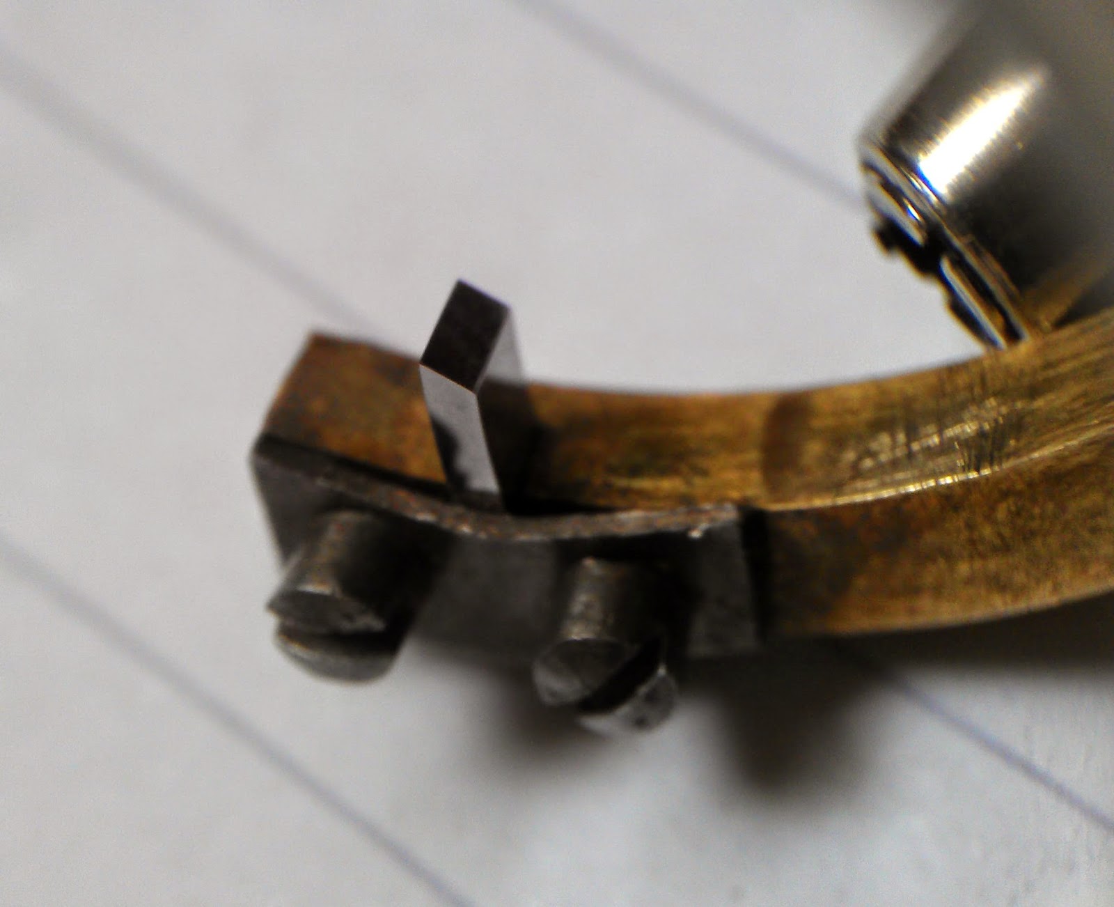
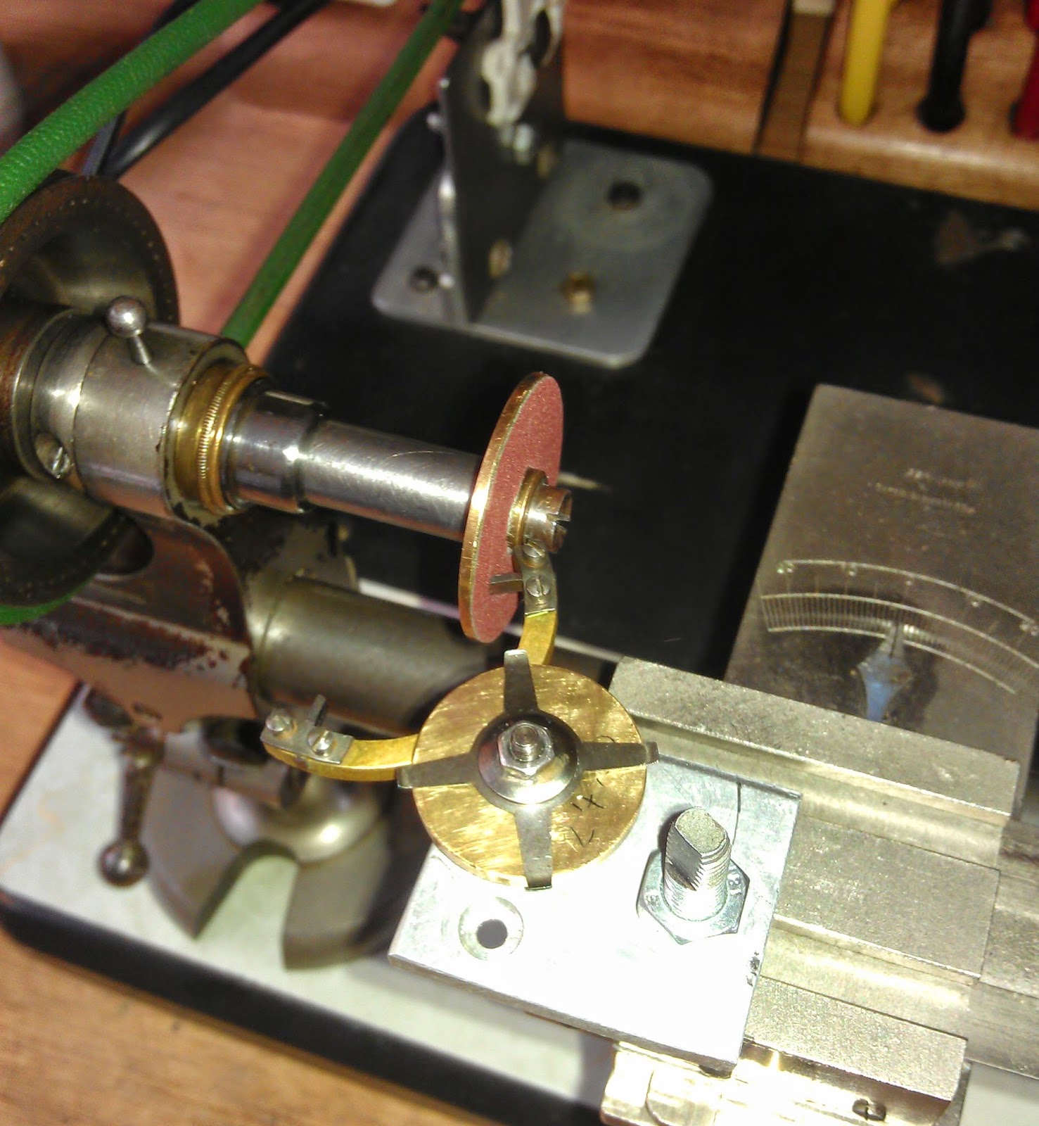
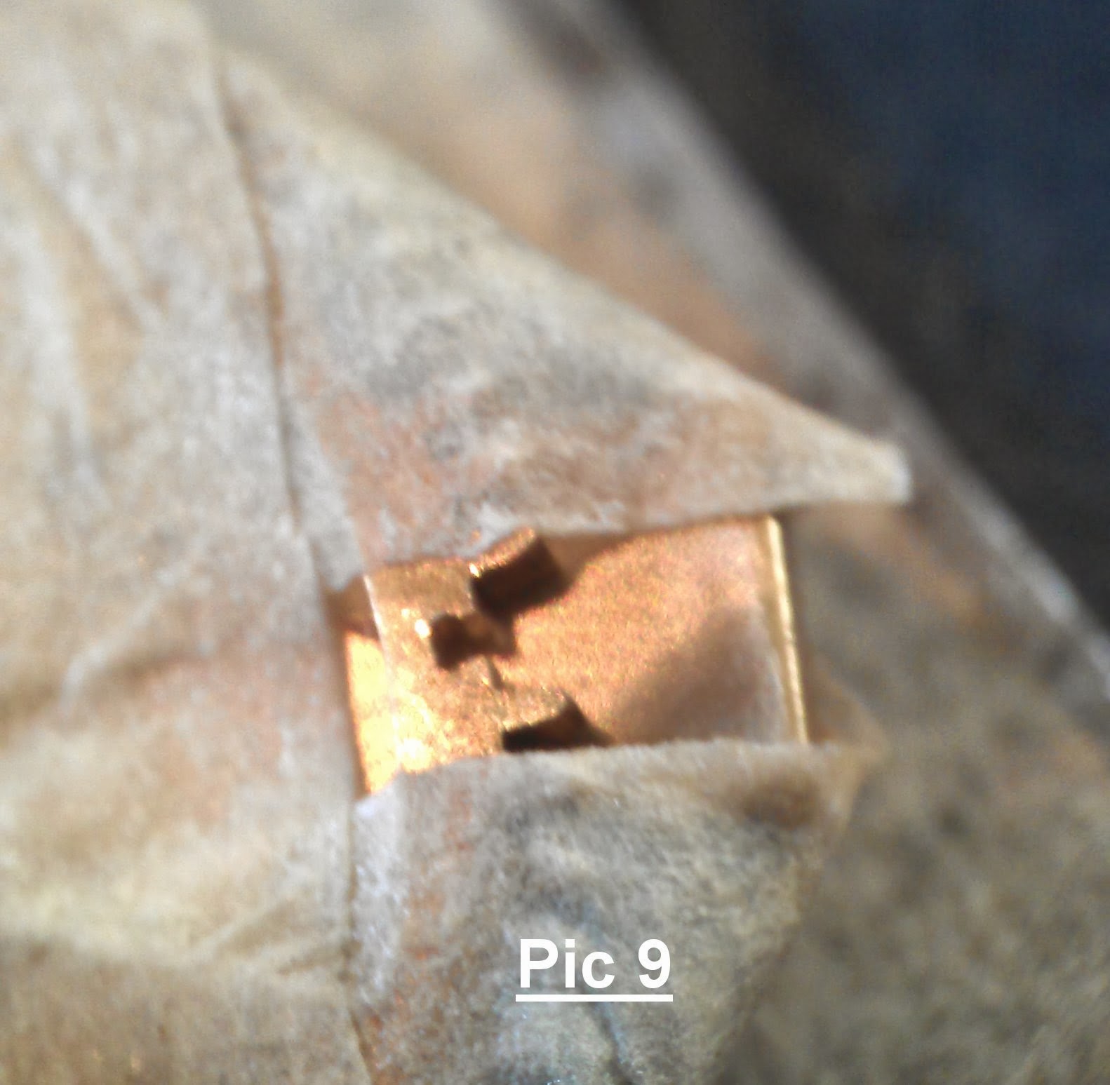
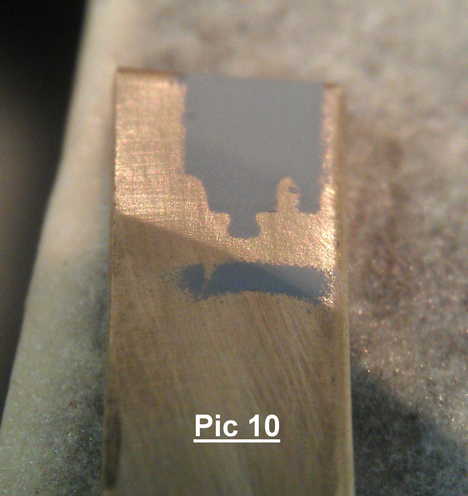
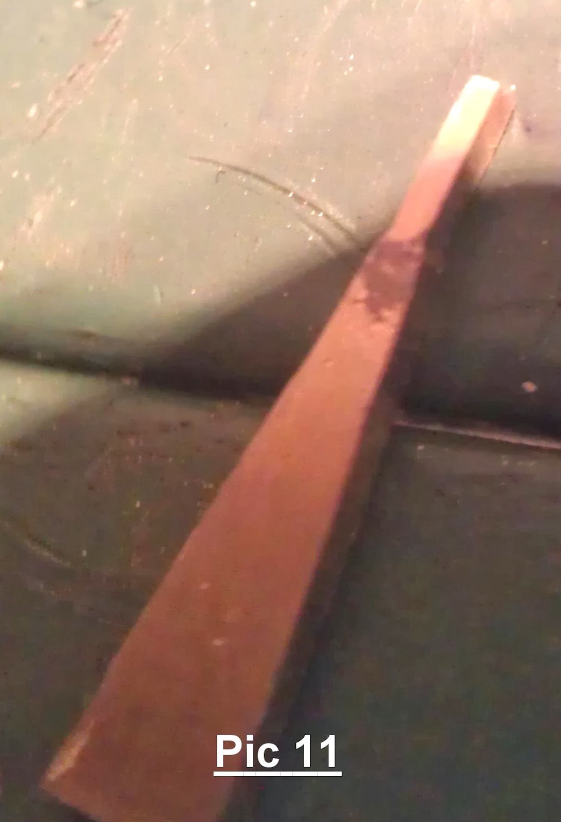
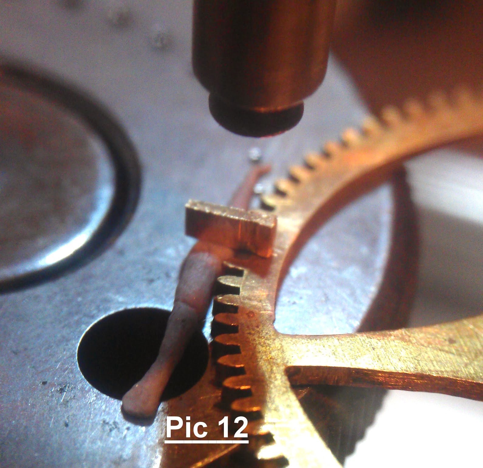
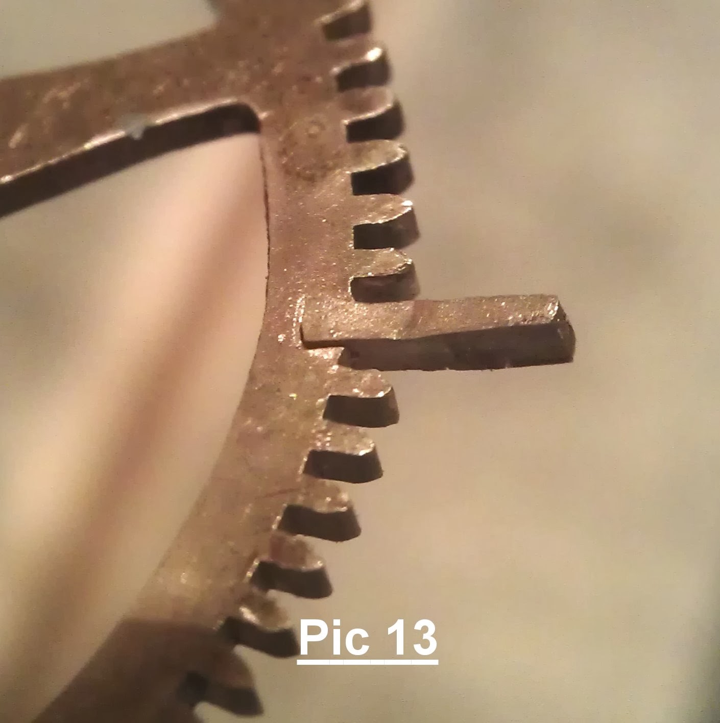
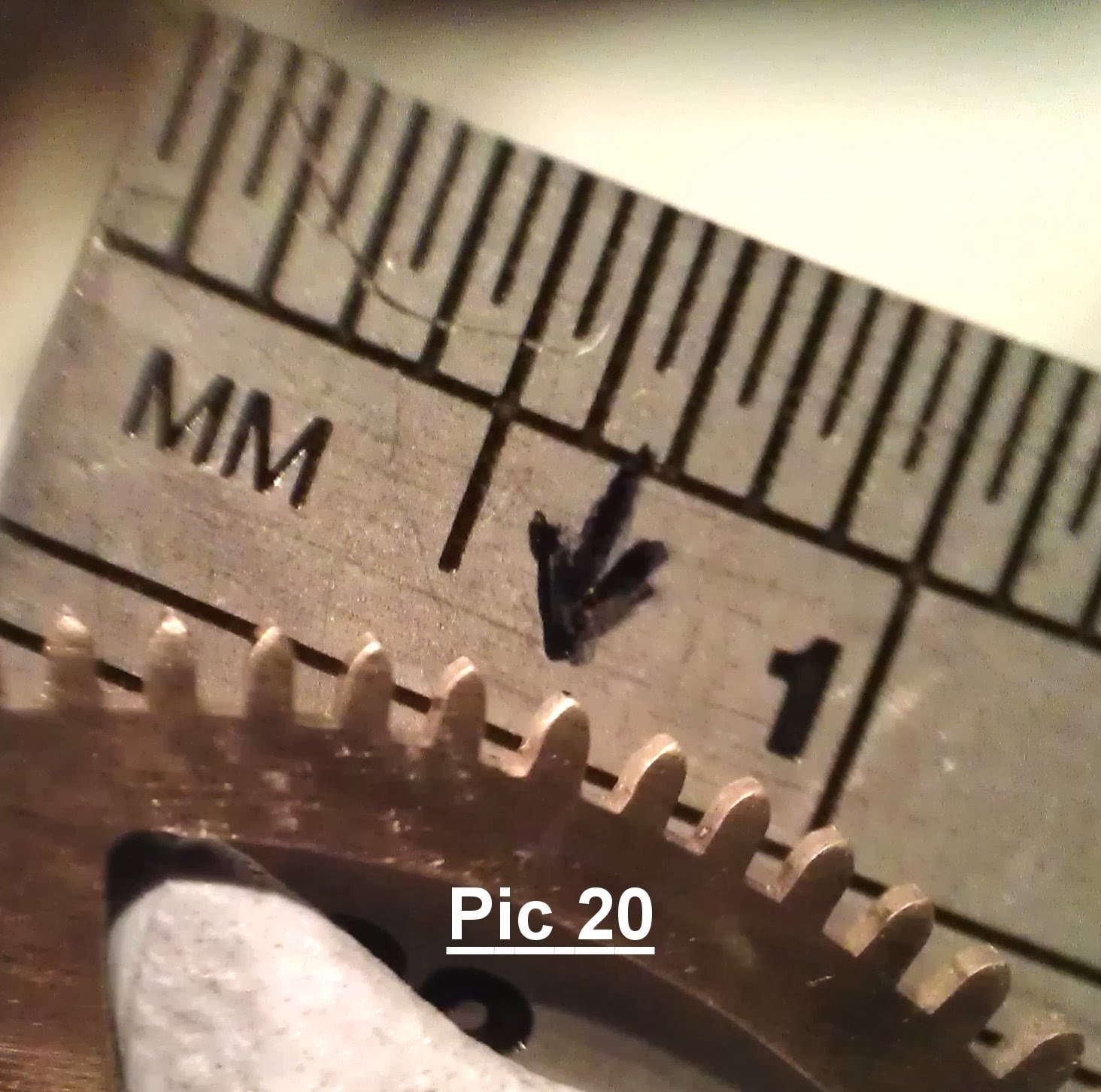
I had a choice, whether to make a complete new unit of ratchet wheel and pipe, or use a new ratchet wheel and keep the original pipe. I chose the latter, though making a completely new unit would be quicker, keeping as many parts original is always the way forward where able. The pipe was mounted in a lathe, and the ratchet was cut off, up to the diameter of the pipe, in order to leave material to produce teeth to fit (rather like castle ramparts) into a new ratchet wheel. See pics below. Receiving slots were cut into the wheel to form a tight friction fit, which was strengthened by riveting and silver solder.
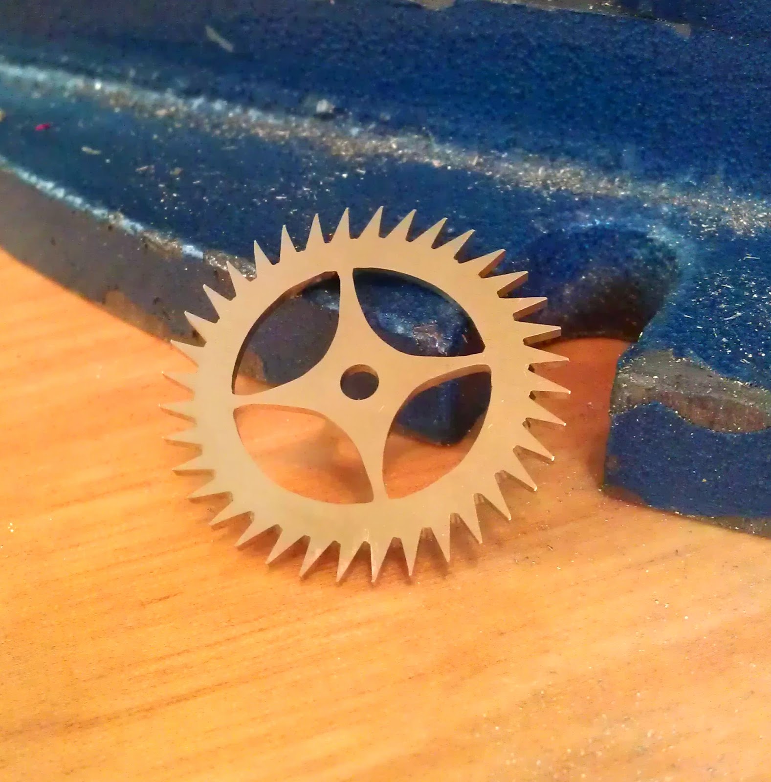
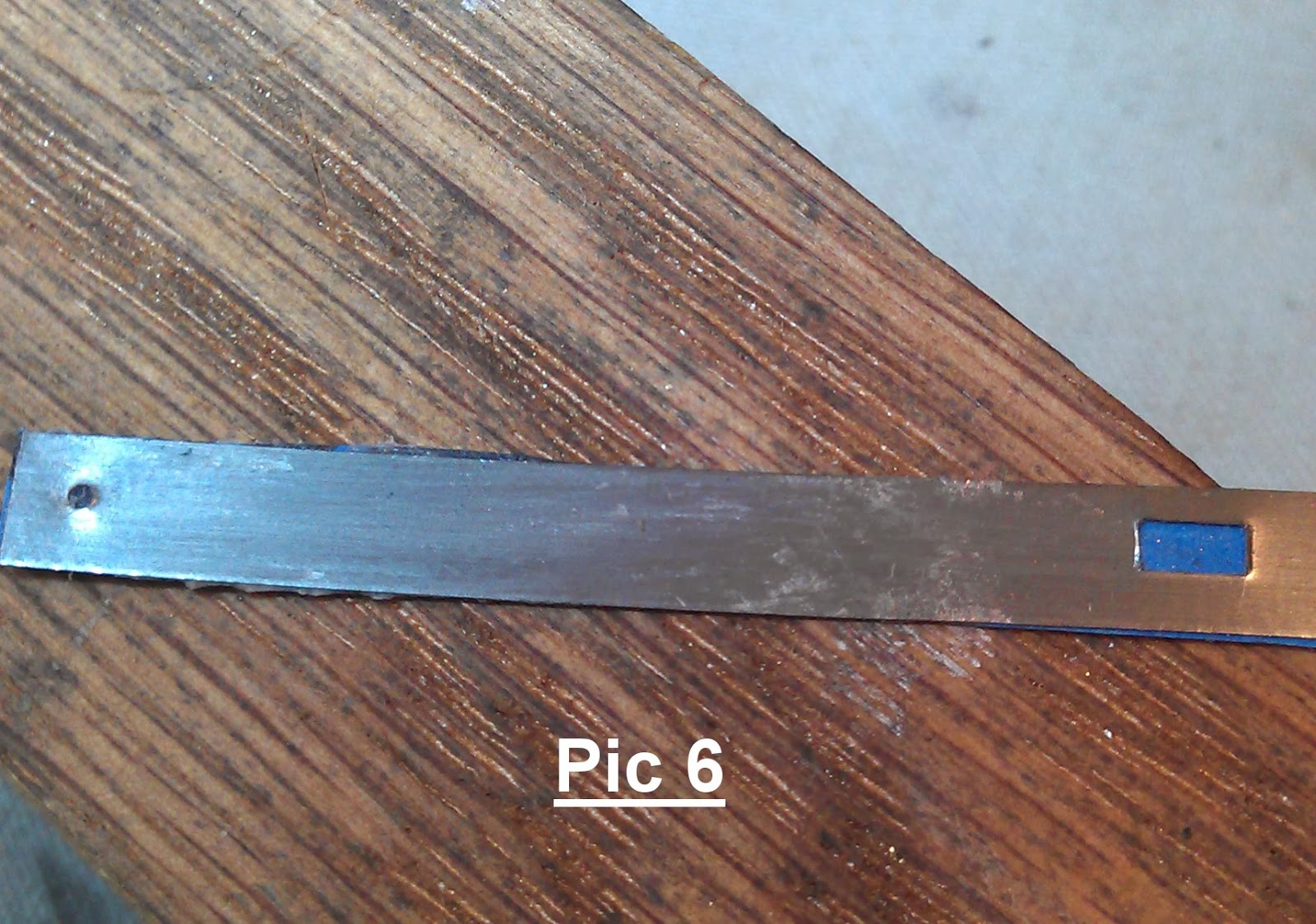
I wasn't expecting to find quite so much work needed on this time only piece. The escapement wheel had irreparable damage to it, with a few tooth tips broken. I also think that the teeth had been shortened at some point and  an attempt made with the anchor to match for geometry. These led to me making a new escapement wheel by hand. It can seen in the pic below that the wheels inner cut outs maintain a hand made sense. Following this I made a new anchor from flat tool steel stock. Following being satisfied the geometry was correct, the new anchor was hardened, polished and tempered.

The lantern pinions required re-trundling given there was wear on them. I will let some wear go with these, however as soon as they begin to look 'squared off' it's time to change them.
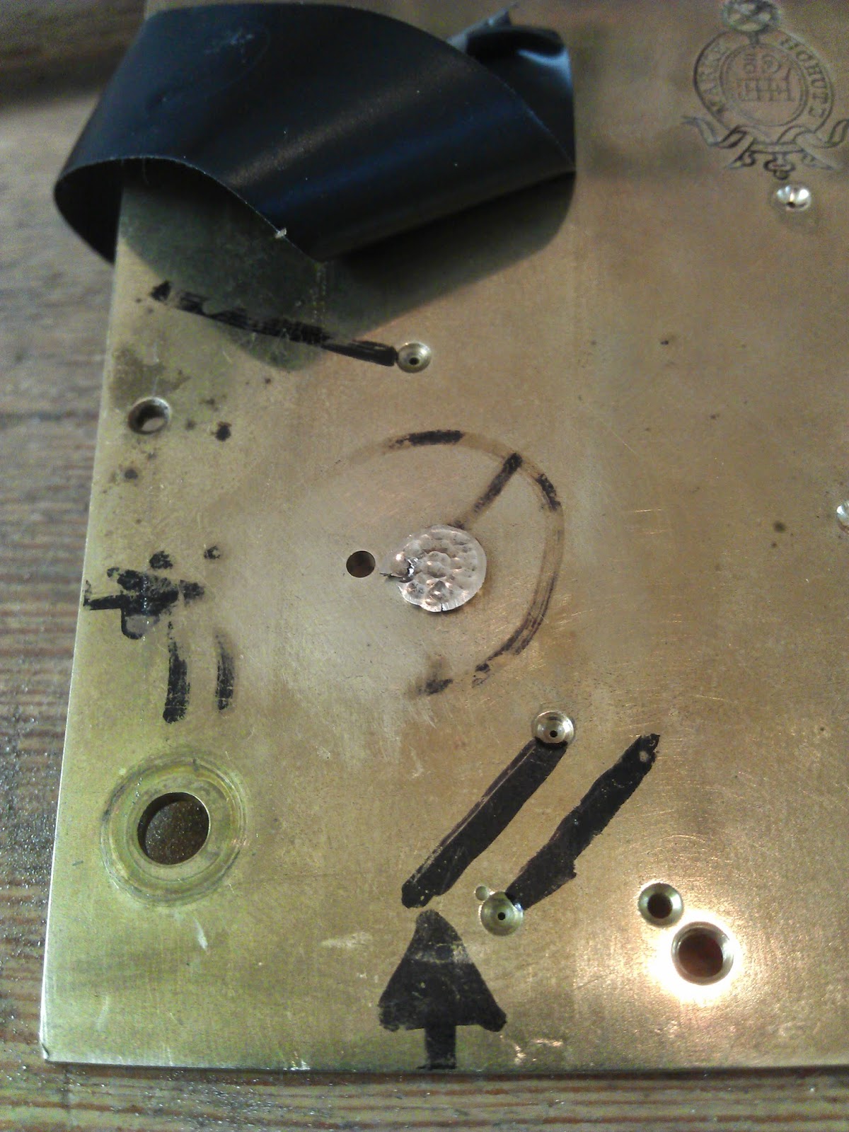
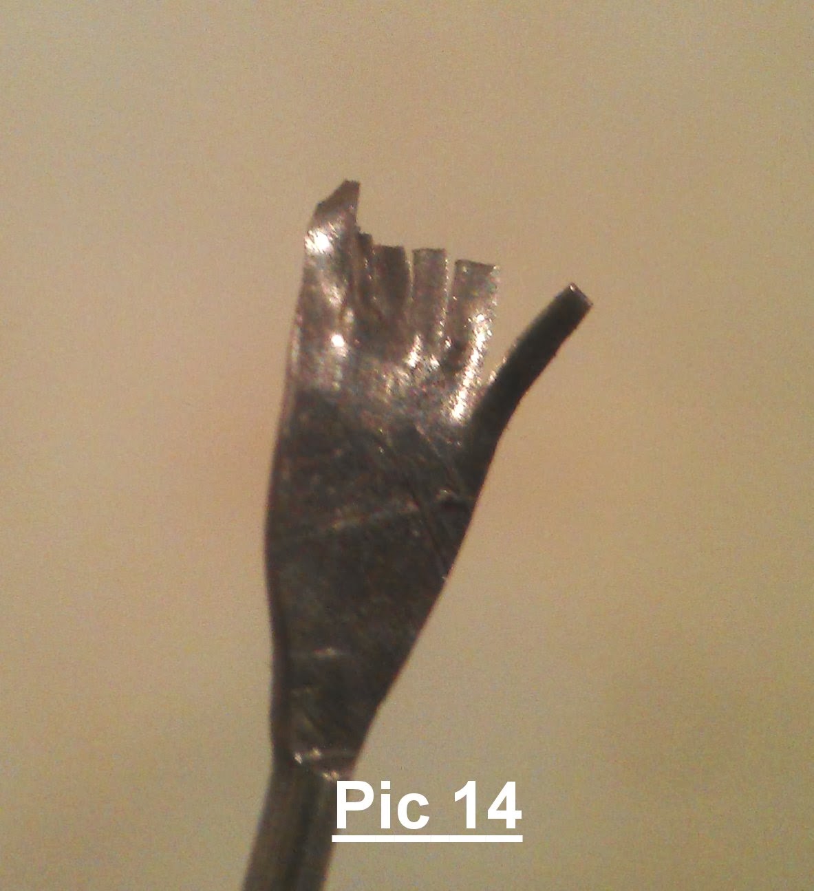
A new barrel spring hook was needed. It can be seen below that someone had attempted to solder the hook  in. It came out with a little wiggle. A new hook was made on the lathe and fitted to the barrel.
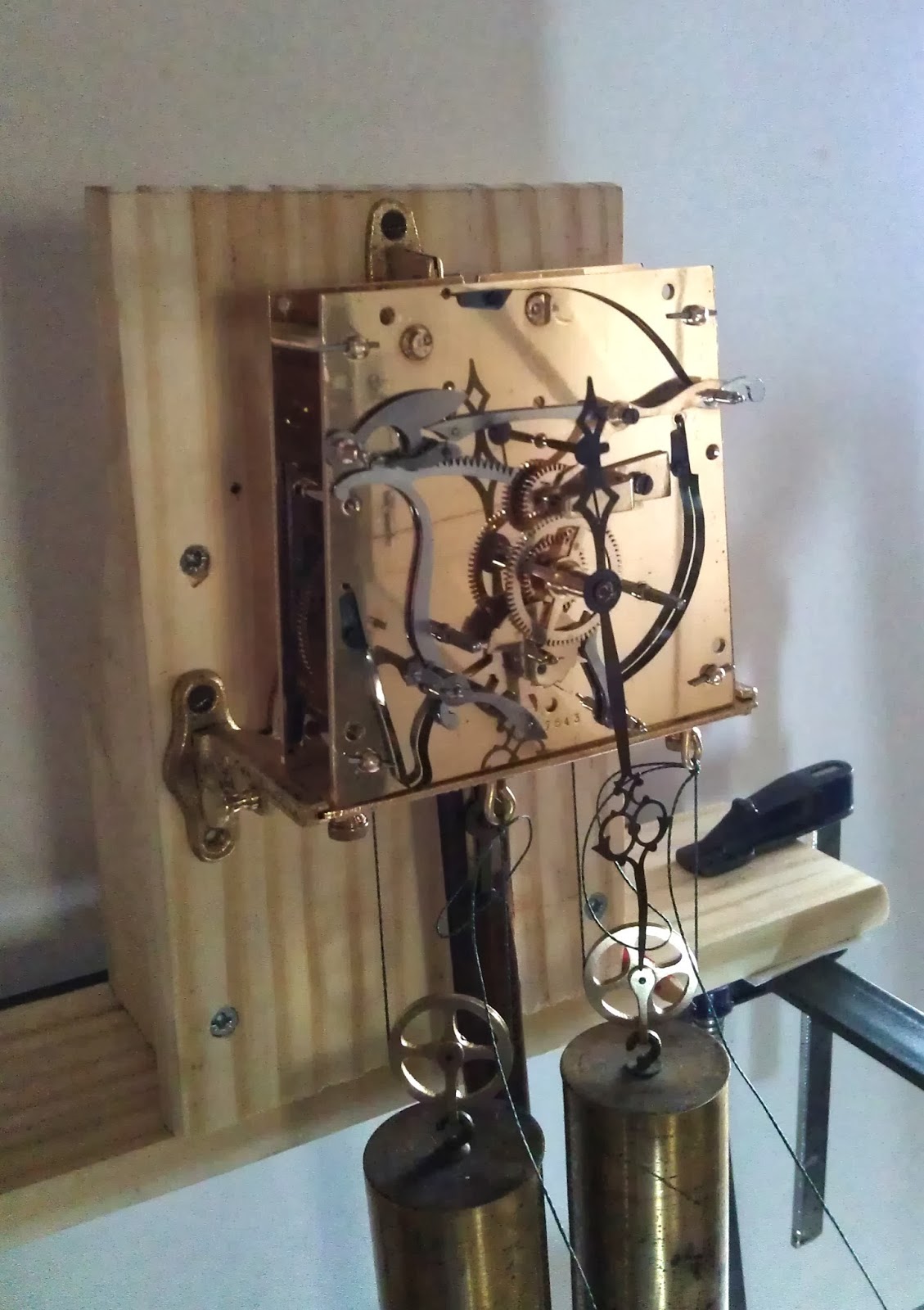
After some pivot hole re-bushing work, pivot polishing/burnishing and a new pivot fitted to the escapement wheel arbour, the movement was reassembled and tested. After some finer adjustments to the escapements drops, the movement runs well and has proved reliable.
As mentioned the case was to get a light touch. The shellac on the case is a little wrinkled but is acceptable. The case had a dust and wipe down with some alcohol, followed by a high quality wax. New brass inlay was fitted where it was missing and the case was complete. The smudging of the numerals on the dial was improved as much as possible and the hands and screws were cleaned, polished and re-blued by heat.
I spent a great deal of time on this clock, far exceeding its value! But I think it was worth it. Please do send me any comments or questions you have, thanks for reading.


Tuesday 27 May 2014

Restoration of a Two Weight Vienna Clock Movement by H. Endler ca1877


This is a fine movement, made by H Endler of Silesia ca 1877. Whilst told it was running when I got it, I did not attach the weights and pendulum and see for my self. The pivot holes were very dirty and dry. The pallet impulse faces looked nasty and there was a really horrible looking Rathburn type bushing attached to the back plate.


These are particularly frowned upon in the horological community. What a terrible shame that somebody did this to this fine movement.

Why?
Given no other bushing working had been done on the movement, and given the position of the Rathburn I can only surmise that, along with discussion with likeminded friends, that it was put there to aid assembly of the strike train. In that the gathering pallet arbour’s position could be adjusted post plate assemble in order to adjust the stop position of the gathering pallet, against the rack.

It can be seen that there are 3 holes left by the Rathburn in the plate. The smallest one was for a locating pin.


I decided to ream the largest hole, taking in the smallest hole with it, and reaming the other on its own. The reamer has a slight taper, allowing the use of a slightly tapered brass plug to be cold fitted/knocked in to the plate. Given the type of movement and where the pivot hole would be in the train i.e. quite high up, I wasn’t  concerned about the friction/load of the arbour popping the brass plug. The taper tight fit would be more than enough. However when gathering pallets are re-fitted to the end of their arbour, they may need a few gentle taps to home them, with a stake. This will put pressure on any bushing on the back plate, and can pop it out. Often clock menders will shim behind the shoulders of the arbour before re-fitting a gather pallet to avoid such an event.

I cut a small chamfer on the inside of the plate, second pic above, to the newly reamed larger hole. And peened into this, pic below. In the same way I would if installing main wheel bushes on a clock plate. Excess brass was removed to original level, and the finish restored.


The new hole for the gathering pallet arbour’s pivot required spotting, so using a depthing gauge the spot where the new pivot hole go should be was marked.

It was drilled using a clock plate bushing tool. The plate could be fixed flat by the tools clamps, and the 0.72mm spade end pivot drill held by the mini chuck. This ensured a perpendicular and accurate entry into the spot punch mark, and ultimately a clean pivot hole.


Following the hole being smoothed, a new oil sink was cut and this task was complete, second pic above. The plate restored to its original appearance.

A couple of bushes were required for a few other pivot holes, however they were in generally good order. A few pivots were a little bent, probably from previous assembly with a little heavy handedness, they were all burnished.

It was apparent somebody had previously had an attempt at re-facing the impulse pallets. At magnification you can see the file marks and the uneven finish. Personally I think they were lucky the clock was running, apparently.


As described in the making of Vulliamy Pallet in another entry on this blog, the pallets must re-faced as perfectly as possible. At the correct angle, and polished to a mirror finish.

A small home made jig was used to fix the verge and pallets onto the cross slide of a watchmakers lathe, ensuring that the tangent line from the brass disc (24.30mm in diameter for this verge) remains in line with the refacing surface, until the surfaces were re-faced perfectly, using different grades of wheel. And finally polish with super fine compound on a buff felt wheel. You can see the difference the right technique makes.


Following a few other service related jobs and repairs the movement was assembled and ready for testing. 
Update. The movement has been on test for two weeks now and has run perfectly, so it will be going back in to its case and on the wall.


Tuesday 25 February 2014

Restoration of Gustav Becker Two Weight Vienna Wall Clock


I managed to get this attractive Gustav Becker for a very reasonable price. It was the price that made my decision, had it cost too much more I may not have bothered given the work required.
The crown at the the top of the clock and bottom pediment are not original to the clock. It is not too unusual for the crown to go missing on these, less usual to have the bottom pediment missing. In the picture above right, the rear of the replacement bottom pediment can be seen. It has been well made, though with ply wood and then veneered with English Oak as had the top crown.
Below is a picture of a very similar Gustav Becker Vienna, which I used as a reference when restoring this one. The crown and the bottom pediment can be seen to be very different to the replacements found on the clock above.

As would be expected, the movement is of a very good quality. Finely made with precision, though very dirty and very oily. After disassembling it was given a thorough clean and reassembled to observe for wear in the pivot holes and the pivots. Each component is carefully inspected under magnification, looking for wear, bent teeth or any signs of metal fatigue. These finer movements often do not need a great deal of bushing work carried out on the pivot holes, however notable wear was evident and a total of 12 pivot holes were re-bushed.
                                                                          

All other aspects associated with a full service and repairs were carried out and the movement was re-assembled. Running the movement on a test stand for a couple of weeks gave the opportunity to work on the case. I wait until everything is ready for assembly before polishing the weights and the pendulum bob. After polishing these I like to coat them in a gold tinted shellac, which protects from tarnish, finger marks and gives a brighter finish.
                                                                       
Case parts were supplied by John at Old and New Times. John makes replacement components based on original designs. Having chosen the case parts it then required the task of matching the wood colours. I used small squares drawn out on a parts of the case components that would not be seen on assembly to test the colours. No two wood dyes form different manufacturers will ever be the same, so it is a case of mixing and testing in the numbered squares drawn out on the wood. It's a good idea to make notes, and use a precise measurement, such as a large plastic syringe, as you go in order to be able to repeat what you've done in a larger batch when happy with the match. It's fair to say it's pretty difficult to get an exact match, and it's a good idea to get a second and third opinion from friends. Ask them to choose the best match out of the test patches on the parts. If they agree with you it's probably close enough!

So here's how the clock looks now it has been finished. In the first picture you can see the pendulum swing with quite a large amplitude. This was reduced greatly by adjusting the locks of the pallets until the escapement wheel teeth were dropping onto the lock faces of the pallets by only approx 0.35-40mm. It now swings approx 18-19mm either side of centre, which does make it more sensitive when beat setting but is my preference to have a small amplitude. It is keeping great time. 


Wednesday 5 February 2014

Tooth Repair on a Fine Clock Wheel

I thought it might be useful, and enjoyable, to show a few techniques I use when repairing/dovetailing a tooth on a French wheel. These teeth are very small and can be challenging to replace. I hope it offers something to someone.

I have used a French wheel from my parts bin.

The tooth in question can clearly seen to be bent in Pic 1.  Before the tooth is  removed, using a sharp scribe, score a line from the centre of the base of the old tooth on the radial line to centre of the wheel, no deeper than half the depth of the rim, pic 2. Once this is scribed the tooth can be carefully taken off using a very fine blade on a jewelers scroll saw; fine enough to fit between the teeth and cut along the line of the wheel circumference.


Using the scroll jaw, cut into the wheel along the scribed radial line to the desired depth, pic 3. Avoid cutting deeper than half of the depth of the wheel rim. When using a scroll saw for these micro jobs I have found the scroll saw easier to use and control if only approx a quarter of a blade is used.

Use the scroll saw to carefully cut the dovetail sides, to the same depth as the centre line already cut, pic 4. The scroll saw can be carefully used to remove any brass in the dovetail hole. Using a very thin cut of 600 grit wet and dry cloth in a ‘to and fro’ motion with both hands will effectively smooth the base of the dovetail, pic 5. Wet and dry paper will break doing this, the fiber backed type is ideal for this.

Finishing or widening the dovetail side is tricky in such a tiny space. My preference here is too use the cheap Indian suspension springs with wet and dry paper glued to one side, pic 6. This technique creates a tool that can work effectively in this small space and also will not abrade other areas of the working space, pic 7.


 Once you’re happy with your dovetail hole, pic 8, cut a piece of donor brass, place it under the dovetail hole, mask the wheel up with tape; holding the donor piece tight to the wheel with the tape, pic 9. Spray the dovetail very lightly with  an aerosol paint and leave to dry. Any paint on the wheel will dissolve in some acetone, and you will have the impression of the dovetail left on the donor brass, pic 10, which will be a great help when cutting the new tooth/dovetail insert with the scroll saw. Leave plenty  of brass at the large end of the donor piece for handling and holding in a vice, pic 11. It will also be a lot easier to find if you drop it, or subconsciously put it down on the bench whilst looking for a different tool.


The donor piece needs to be a tight fit. It is a good idea, with a very fine paint brush , to apply a little solder flux in the joint before fitting. I use Tix flux and solder.
When you are happy that it will go in with a little gentle persuasion, I have found the best way is using a staking tool and a small piece of ‘Bluetac’, pic 12, a little tap with a brass ended flat punch will fit the piece squarely. Ensure there is excess donor brass either side of the wheel, and using a steel flat punch in the staking tool, ‘peen’ the donor brass to fit/fill the dovetail hole well, pic 13. This is why the flux has already been applied in the joint.


Only very tiny chips of solder are needed for the joint, It is helpful to squash the solder in smooth nose pliers, cut teeth longways and then trim tiny pieces off and place them on the seams on the joint, pic 14. This needs doing under mag, I use 10x for this as I like to have the solder pieces ‘standing up’ as in the picture. Placing the solder in this way I find that the solder, melts, drops and flows straight into the joint and much less on the wheel rim, pic 15/16.


A mini butane soldering torch with a fine hot air nozzle attachment, to ensure there is no flame, and at a low/med heat from underneath does a great job. Some prefer other heat sources, including alcohol lamps. After it has cooled clean off any flux thoroughly.


I prefer to leave a ‘long tooth’ throughout, up until the next stage, as it is easier to see that the new tooth is still on the radial line. When cutting off the excess tooth, and filing to length it is a good idea to protect the adjacent teeth tips with tape, and keep checking it has not been breached, pic 17.


If the gaps between the new tooth and adjacent teeth has been compromised, by solder for example, it can be very tricky to ‘make good’ in such a small gap. Get another of those cheap Indian suspension springs, put it in the vice, and ‘skip’ a needle file across its edge to give it very fine teeth, pic 18. Using this will make a good job of re-defining the 90deg root angle of the tooth in the gap, where most files will not fit, pic 19.


If the new tooth is too wide, use the suspension spring with the wet and dry paper stuck to it to reduce its width. Again, using this will ensure only the width is abraded, not the gaps base. These can also be used to finely finish the tooth’s profile. Carefully remove excess brass from the tooth to match the wheel rim width, with damaging/marking the rim. The dovetail can be carefully finished/polished with very fine wet and dry paper, to a point where it is virtually invisible to the naked eye.
When using files to shape the tooth, it is best to use as fine a file as you can, cut grade 4 and above. ‘Escapement’ files are smaller than other needle files, for shaping the top of the tooth a Barette/safety escapement file is ideal. Good ones are not cheap, and should be saved for delicate jobs.