I'd like to thank David La Bounty for his invaluable technical advice and Ken Simmons for the use and support with his industrial size lathe to machine the original piece of tool steel. My clock maker lathes were simply not big enough to perform the original cut!
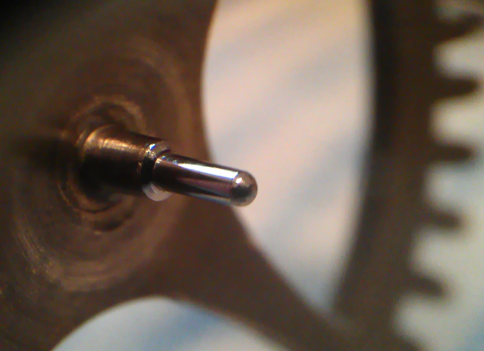
The wear on the original pallets can be clearly seen in the
picture below. Ordinarily it might be possible to grind and polish the impulse
faces, and refit. However I think these have had that done before now, as they
are quite short, leaving little room to remove enough steel to give a clean
face. Unfortunately the existing ones
are not reversible; i.e. where the pallet can be turned and fitted in the
opposite verge arm, as both ends have been ground. So completely new pallets
required making. This will mean that a complete ring will need to be made in
order to ensure that the curvature of the nibs is as required, and the nibs then
cut out of the completed ring.

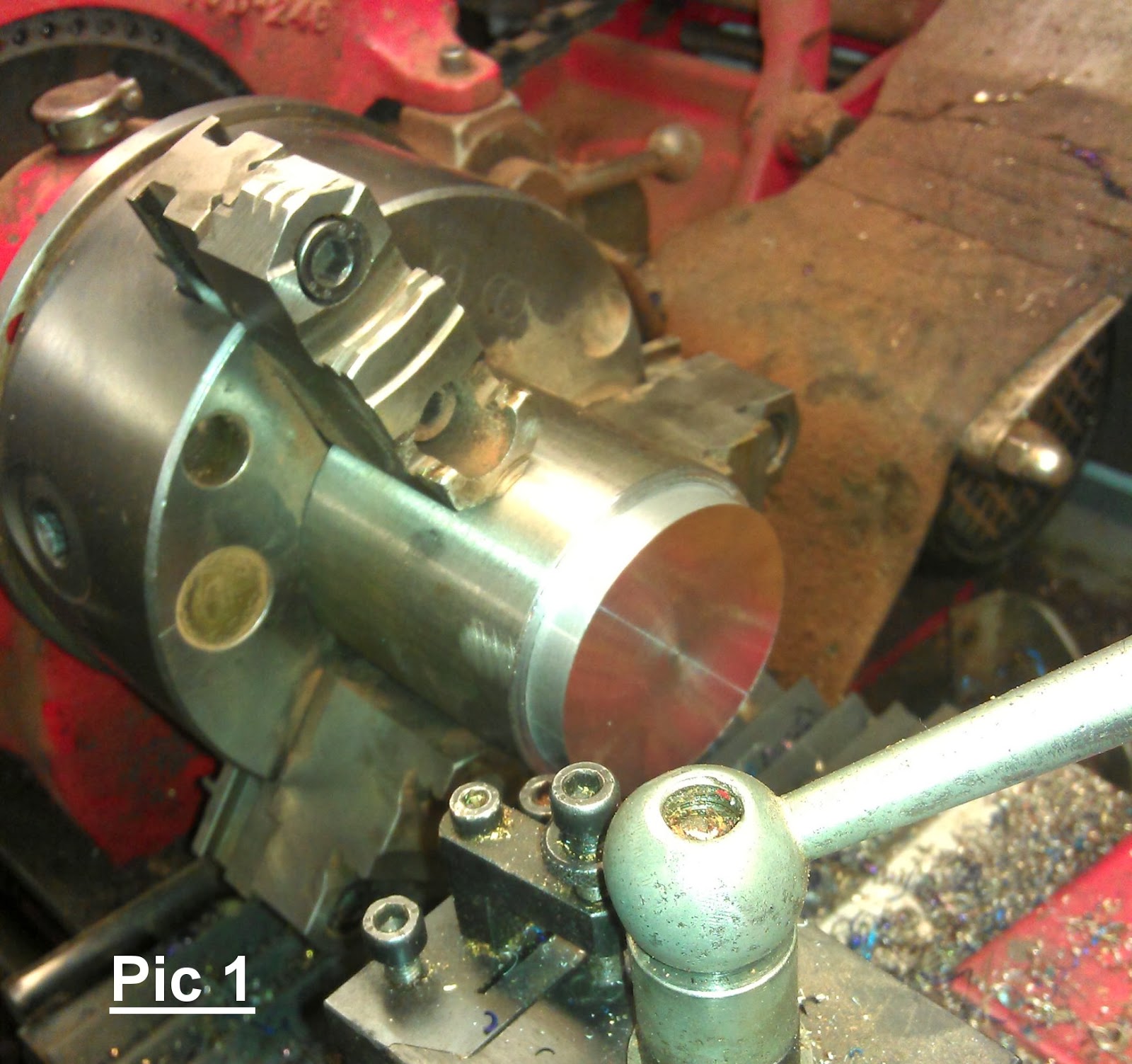
In picture 1 the
60mm tool steel rod can be seem in the lathe chuck. It is quite a piece of
steel given how small the pallet nibs will be. The outside diameter of the ring
required is ascertained from measurements already known, i.e. the distance from
the centre of the verge arbor, to the outer edge of one of the existing pallets
= 51.68mm.
The inside diameter is taken from the Outside diameter minus
the thickness of the pallet nib required.
= 51.68mm – 0.94mm =
50.74mm
The outside diameter is cut first and polished
whilst on the lathe, not just for convenience, as the thickness of the ring can then be measured as the boring out of the internal diameter actually progresses (picture 2), using the outside finished
and polished diameter as a constant, given there will be no further material
removed from the outer diameter.
In picture 3 the ring can be
seen to just beginning to locate in the verge. This was enough of a cut for
now, as any surplus material on the internal diameter would be taken off in a
polishing process.
There was a good amount of chatter when commencing parting off the ring from the steel rod, despite the tool being very
sharp and central, and kept close to the tool post. So I adjusted the cutting
tool to give a slightly negative cutting rake, i.e. the cutting edge was
sloping downward by a degree or two. The parting tool was also ground with a slight
rake across its width in order that the cutting edge (on the right edge) meant
the ring parted from the rod with very clean edge. The tool
adjustments made quite a difference and parting off was clean.


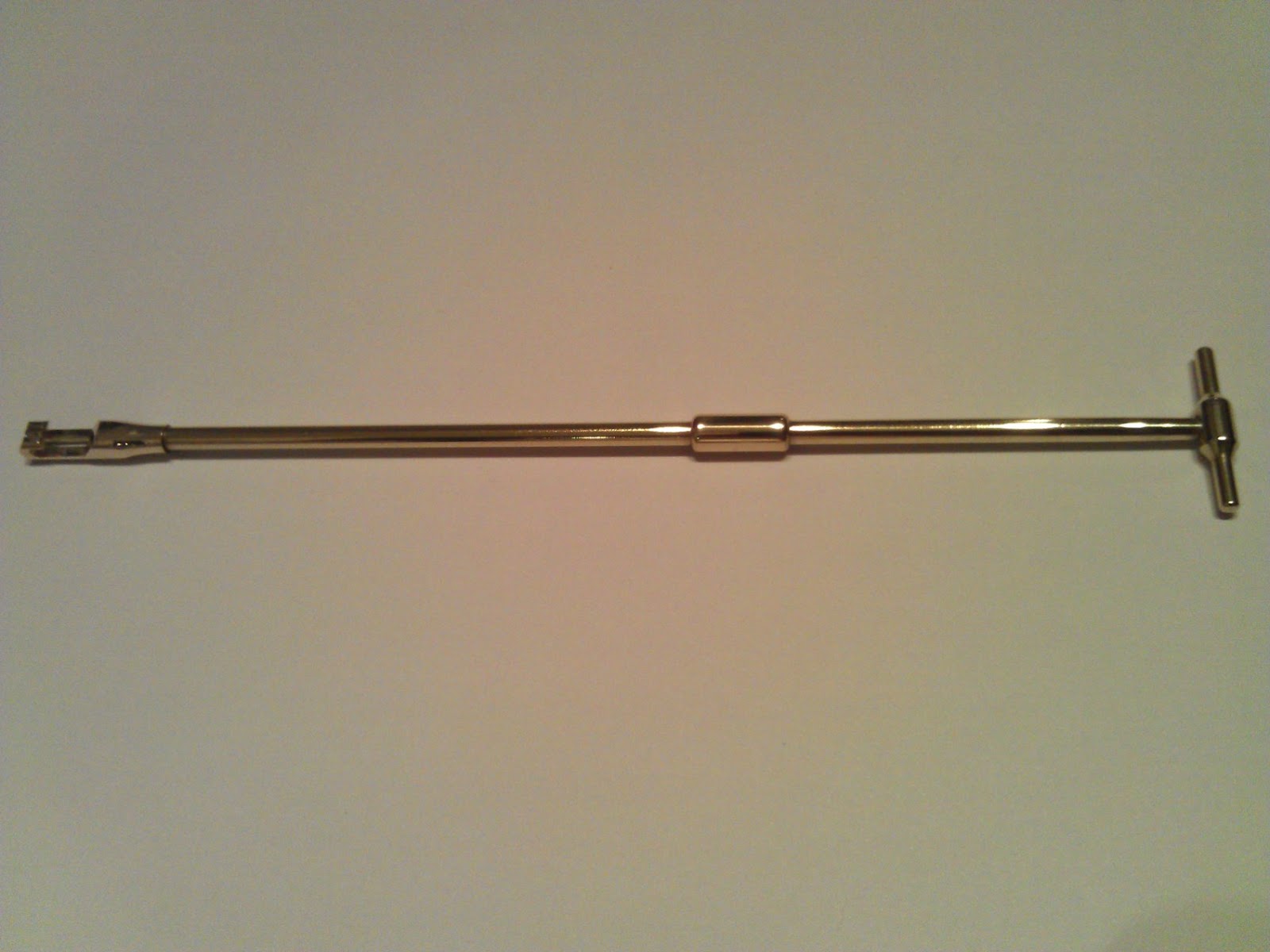
In picture 4 the ring can be seen to be mounted in a small
chuck on my Lorch 6mm lathe, the jaws have been reversed to accommodate it.
However holding the ring too tightly ran the risk of distorting it, so small
pieces of thick double sided tape were used to hold it in situ, whilst the jaws
were minimally tightened. Round wooden dowling was used, loaded with emery
paper, to polish the Internal diameter. From 600grit through to 7000grit, in
stages.
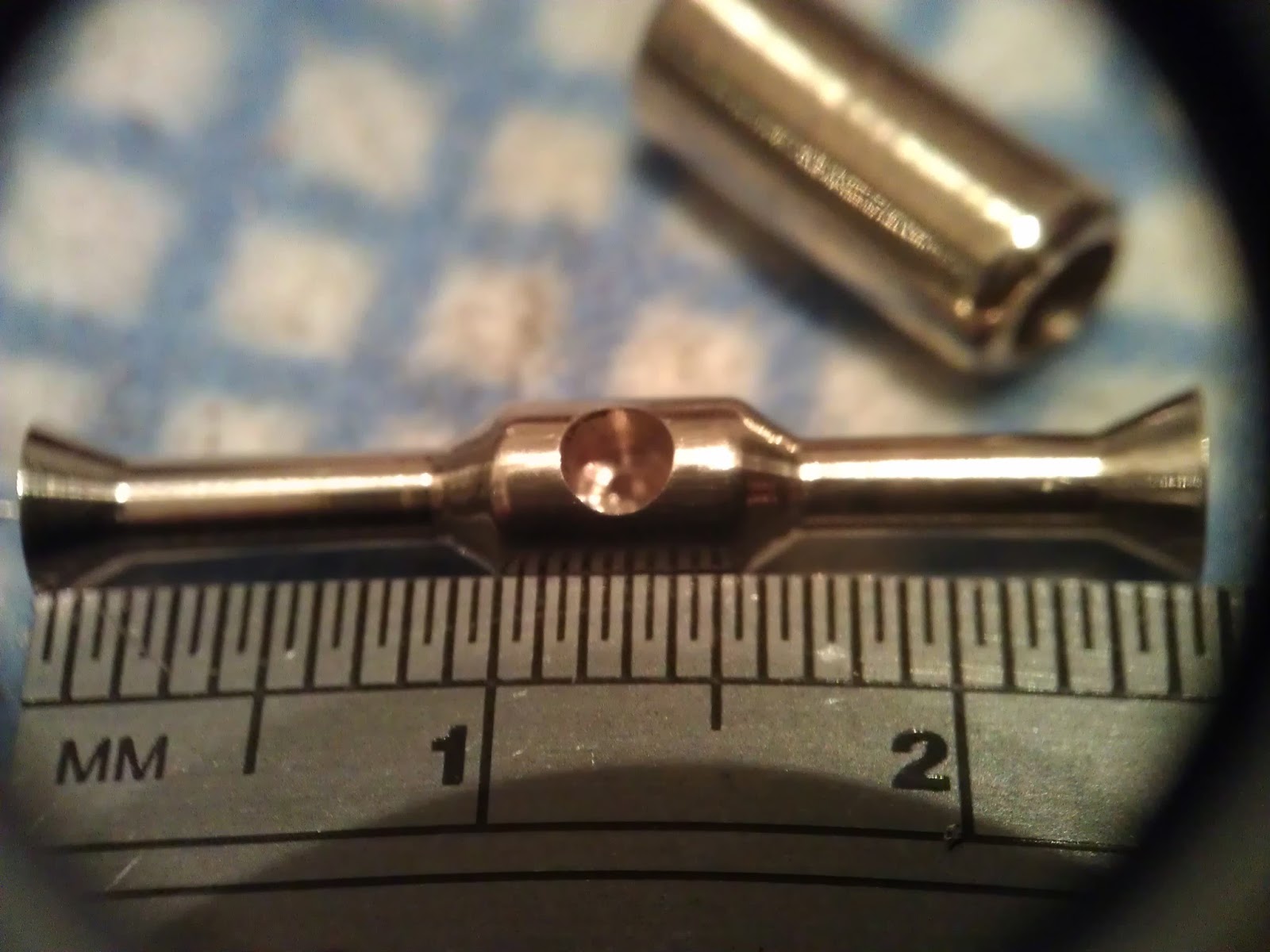
Picture 5 shows the completed ring sitting snugly in
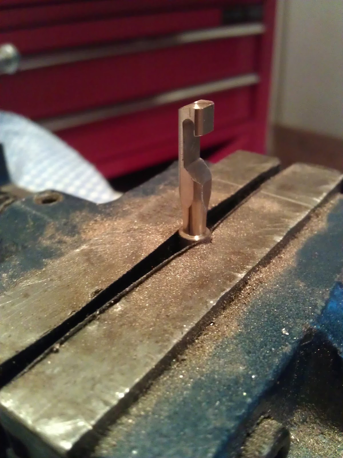
both slots in the verge. Clamping the ring between two thin pieces of wood (Picture 7) in a vice gave support for
cutting lengths off to make the nibs. This ensured that the jewellers scroll
blade did not ‘skip’ across its polished face, undoing all the polishing work.
It also held the cut length in situ until the blade was all the way through,
ensuring a very clean cut.


Picture 6 shows
the jig I made to hold the verge during the process of grinding and polishing
the impulse faces on the nibs. This could
be mounted on the cross slide of my Lorch lathe. The verge must be able
to ‘swing’ on a constant axis point onto the face of the grinding and polishing
wheels, yet still be held firmly in order to discourage any chatter. I used a
modified old centre wheel spider spring for applying tension onto the brass
disc holding the verge to the aluminium plate. Hence the tension was adjustable.
The brass disc was turned to have a radius of exactly half that of the
measurement between the centre of the verge arbor and the dead centre of the
pallet nib. This measurement meant that a tangent line from the edge of the
brass disc could be aligned with the face of the grinding and polishing wheels,
ensuring an impulse face of 2° would be ground/polished, picture 8 and 9.


Picture 11 shows the exit side pallet being ground, and the tangent line mentioned earlier. The brass wheel in picture 9 was made for sticking the emery paper onto for finer grinding and polishing. Once the brass wheel’s desired diameter was cut, its front and back was faced off on the lathe to ensure it turned square and flat to the pallet nibs impulse face. If it does not run square and true the impulse face could be ‘buffeted’ by the wheel and lead to a lesser finish. After using the grinding wheel for removing the initial amount of steel, I used cut discs of emery paper, stuck to the brass wheel with a spray glue. It does not take much glue to stick these on satisfactorily.
When using the emery paper on the brass wheel, once the face
has been ground on that grade, moving the pallet nib impulse face slowly across
the paper using the cross slide, whilst keeping light pressure on it with my
finger, effectively removes any lines left by the paper. This is especially
effective during the last polish. Grades of paper used in sequence were grits
600, 1000, 1200, 2500, 3000, 5000, 7000.
It’s a good idea to check your tangent line after changing the
grade of paper, given they differ in thickness.
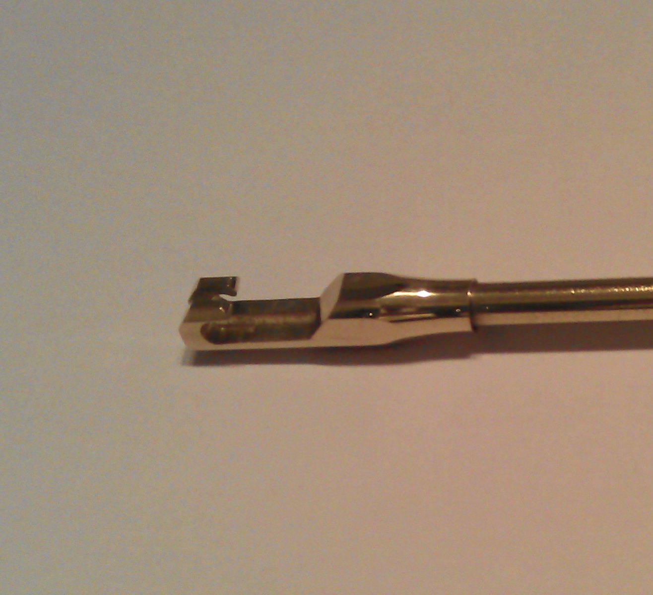
Pictures 10 and 12 show the finished pallet nibs, with clean
edges and even impulse faces. They are hardened by heating to cherry red and
quenched, followed by tempering to very light straw colour and quenched again. Followed
by a final impulse face polish on the jig set up, polish of the locking face
with 7000grit, and finally polished using a felt buffer and a super finish
polishing compound.